
phase interpolator

A phase interpolator, maximum technology, applied in the direction of phase shifter, pulse processing, digital transmission system, etc., to achieve the effect of phase error reduction and voltage fluctuation suppression

Active Publication Date: 2017-04-26
MEGACHIPS
View PDF6 Cites 0 Cited by
  • Summary
  • Abstract
  • Description
  • Claims
  • Application Information

AI Technical Summary

Problems solved by technology

[0016] As a result, the phase interpolator disclosed in Patent Document 1 requires four times larger total current supply capability, and requires a larger total area for supplying current sources

Method used


Image

  • phase interpolator
  • phase interpolator
  • phase interpolator

Examples


Embodiment Construction

[0059] An exemplary phase interpolator according to the present disclosure will be explained with reference to preferred embodiments shown in the accompanying drawings.

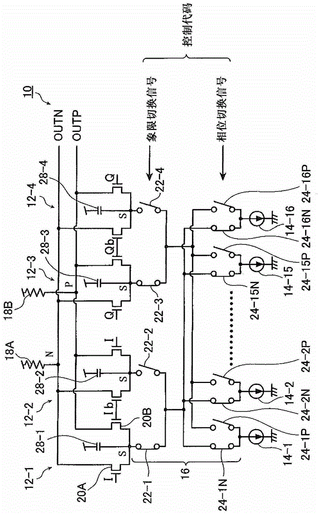
[0060] figure 1 is a circuit diagram showing the configuration of an exemplary phase interpolator according to the present disclosure. figure 1 The exemplary phase interpolator 10 shown in Figure 12 The known phase interpolator 32 shown in has essentially the same construction, but further includes stabilizing capacitors. That is, the phase interpolator 10 includes four differential pairs 12-1 to 12-4, sixteen current sources 14-1 to 14-16, a set of switches 16, two load resistors 18A and 18B, and further includes four stabilizing capacitors 28-1 to 28-4. The basic operation of the exemplary phase interpolator 10 is the same as the phase interpolator 32 .

[0061] Differential pair 12 - 1 includes NMOS 20A and 20B whose sources are coupled to each other to form source coupling node S . Differential inp...


PUM


Abstract

A phase interpolator includes first to fourth differential pairs. Each of the differential pairs includes first and second transistors, and a stabilizing capacitor connected between the source coupling node and a reference voltage. The phase interpolator also includes: a plurality of current sources; and a set of switches that switch connections between the source coupling nodes of the differential pair and the current sources such that (i) a first operating current is supplied to the first and second differential the first selected differential pair of the pair, and such that (ii) the second operating current is supplied to the second selected differential pair of the third and fourth differential pairs. The drains of the first transistors in the differential pair are commonly connected, and the drains of the second transistors in the differential pair are commonly connected to form first and second output nodes such that a differential output signal is output.

Description

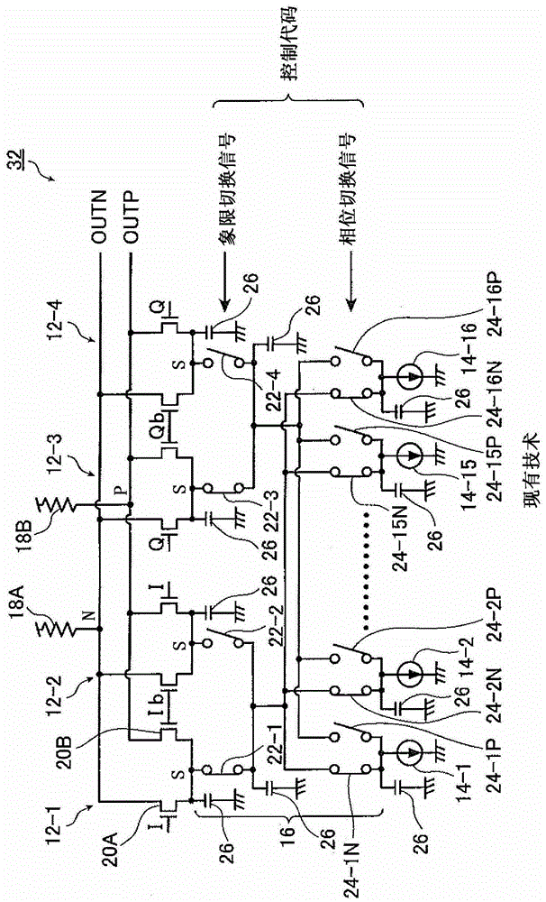
technical field [0001] The present disclosure relates to phase interpolators that interpolate between phases of a plurality of differential input signals to produce a differential output signal having a desired phase. Background technique [0002] Figure 12 is a circuit diagram showing the construction of a known phase interpolator. Figure 12 The phase interpolator 32 shown in FIG. 2 receives input signals I, Q, Ib, and Qb, which are four-phase signals that are 90° out of phase with each other. That is, the phase interpolator 32 divides the entire cycle of the reference clock signal into first to fourth quadrants with the input signals I, Ib, Q, and Qb, as Figure 13 is shown in , and interpolates between the phases of these input signals. [0003] Phase interpolator 32 includes four differential pairs 12-1 to 12-4, sixteen current sources 14-1 to 14-16, a set of switches 16, and two load resistors 18A and 18B . Each of the differential pairs 12 - 1 to 12 - 4 includes t...

Claims


Application Information

Patent Timeline
Patent Type & Authority Patents(China)
IPC IPC(8): H03K5/13
CPCH03K2005/00286H03K5/1252H04L7/0025
Inventor 柳泽畅大
Owner MEGACHIPS
Learn More