A dual-diaphragm speaker module

A loudspeaker module and loudspeaker technology, applied in the direction of loudspeaker transducer fixation, diaphragm fixation/tightening, sensors, etc.

Active Publication Date: 2015-09-02
GOERTEK INC
View PDF3 Cites 0 Cited by
  • Summary
  • Abstract
  • Description
  • Claims
  • Application Information

AI Technical Summary

Problems solved by technology

But there is no application structure that the multifunctional loudspeaker of this structure is used in a module or other electronic devices at present.

Method used


Image

  • A dual-diaphragm speaker module
  • A dual-diaphragm speaker module
  • A dual-diaphragm speaker module

Examples


Embodiment 1

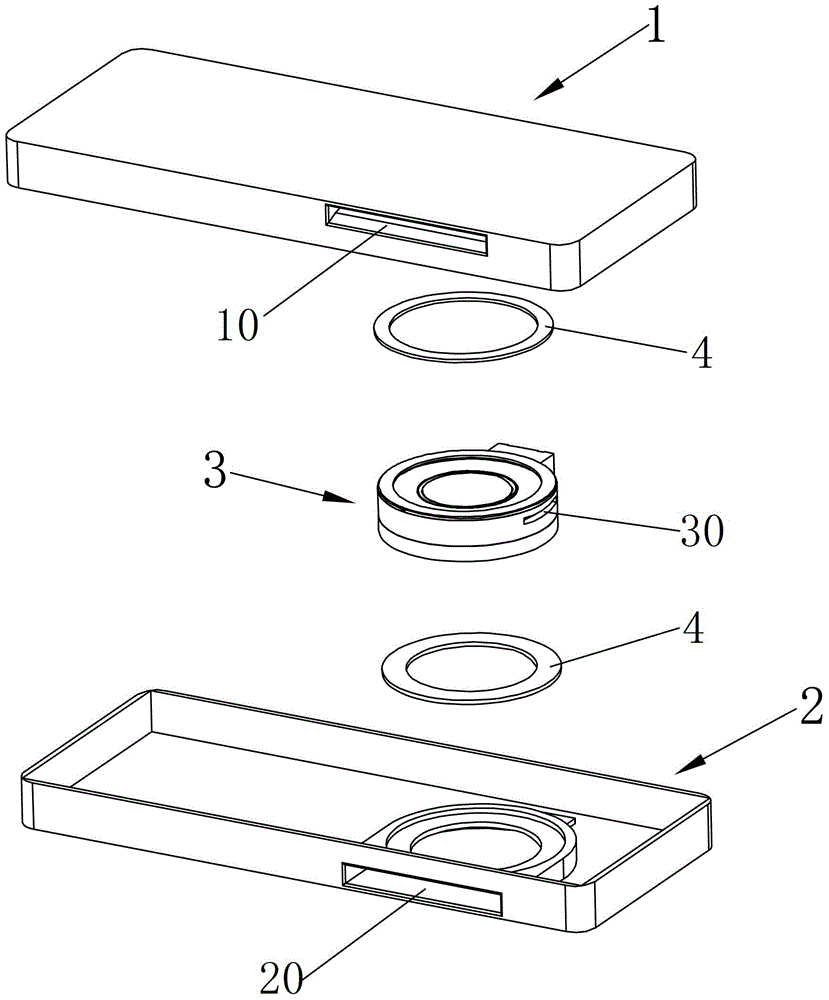
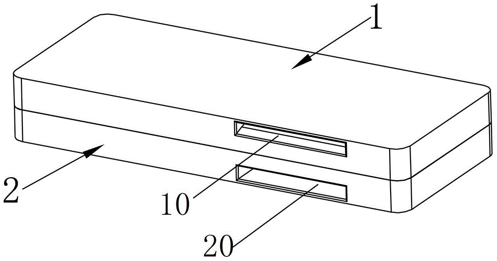
[0027] like figure 1 and figure 2 As shown, the loudspeaker module of the present invention includes a loudspeaker unit 3 and a peripheral housing that accommodates and fixes the loudspeaker unit 3, wherein the upper surface and the lower surface of the loudspeaker unit 3 that are fixedly combined with the peripheral housing are also respectively combined with elastic buffers. Part 4, the elastic buffer part 4 in this embodiment can be foam or spring pad. In order to facilitate the assembly of the speaker module, the peripheral casing is divided into two independent parts: the first casing 1 and the second casing 2. During the assembly process, the speaker unit 3 and the elastic buffer 4 can be combined with the first casing 1. (or the second shell 2) after assembly, then the second shell 2 (or the first shell 1) is combined with the first shell 1 (or the second shell 2), and then glued or ultrasonically welded The first housing 1 and the second housing 2 are fixedly combin...

Embodiment 2

[0037] like Figure 6 and Figure 7 As shown, the speaker module of this embodiment includes a speaker unit 3 , an outer casing for accommodating and fixing the speaker unit 3 , and elastic buffers 4 combined with the edges of both sides of the speaker unit 3 . The peripheral shell is divided into two parts: the first shell 1' and the second shell 2; the main difference between this embodiment and the first embodiment is that the first sound hole 10' is set on the first shell 1' On the surface, the side of the second housing 2 is provided with a second sound hole 20 . In addition, the side of the speaker unit 3 is also provided with a sound leakage hole 30 connecting the rear acoustic cavity of the speaker module and the inner side of the speaker unit 3 . In this embodiment, the first sound outlet 10' is divided into a plurality of strip structures by the outer casing, and this structure has a better dustproof effect. Preferably, the first sound outlet 10' is located on the ...


PUM


Abstract

The present invention provides a double-vibrating-diaphragm loudspeaker module. The double-vibrating-diaphragm loudspeaker module comprises: a peripheral housing providing with a first sound outlet hole and a second sound outlet hole; a supporting structure fixed on an inner wall of the peripheral housing; and a loudspeaker unit comprising a first vibrating diaphragm, a sound coil, a magnetic circuit system and a second vibrating diaphragm. The sound coil and the magnetic circuit system are separately combined with the first vibrating diaphragm and the second vibrating diaphragm. The sound coil is accommodated in a magnetic gap of the magnetic circuit system. Edges of the first vibrating diaphragm and the second vibrating diaphragm are fixed on the supporting structure. The peripheral housing, the supporting structure and the loudspeaker unit form a first front sound cavity, a second front sound cavity, and a rear sound cavity. The first front sound cavity comprises a space between the first vibrating diaphragm and a part closing to the first vibrating diaphragm, of the peripheral housing, and communicates with the external by using the first sound outlet hole. The second front sound cavity comprises a space between the second vibrating diaphragm and a part closing to the second vibrating diaphragm, of the peripheral housing, and communicates with the external by using the second sound outlet hole. The rear sound cavity comprises a space between the first vibrating diaphragm and the second vibrating diaphragm and forms a sealed hollow cavity. The double-vibrating-diaphragm loudspeaker group can improve high and low frequency acoustic features.

Description

technical field [0001] The invention relates to the field of electroacoustics, in particular to a speaker module with double diaphragms. Background technique [0002] At present, multifunctional speakers with a vibration function are widely used, and the multifunctional speakers with this structure have both the functions of a speaker and a vibration motor. The magnetic circuit system in this multi-functional loudspeaker is not fixed on the casing as a vibrator, but is fixedly supported by an elastic support member, and the magnetic circuit system can generate a vibration feeling when vibrating. Due to the low resonant frequency of the magnetic circuit system, the vibration of the magnetic circuit system produces obvious vibration under low frequency conditions, but the vibration of the vibration system is not obvious. At this time, the multi-functional speaker is used as a vibration motor; The vibration of the system is not obvious, but the vibration of the vibration syste...

Claims


Application Information

Patent Timeline
Patent Type & Authority Patents(China)
IPC IPC(8): H04R9/06H04R9/02
CPCH04R9/06H04R1/02H04R1/2807H04R1/24H04R1/025H04R9/02H04R1/28H04R7/18H04R9/063H04R2400/07
Inventor 杨健斌江超
Owner GOERTEK INC
Why Eureka
Try Eureka