A printed coil, its manufacturing method and earphone receiver

A technology of printing coils and manufacturing methods, which is applied in the field of receivers, and can solve the problems of low power of earphone receivers, polluted environment, high height of earphone receivers, etc.

Active Publication Date: 2020-10-27
BESTAR HLDG
View PDF3 Cites 0 Cited by
  • Summary
  • Abstract
  • Description
  • Claims
  • Application Information

AI Technical Summary

Problems solved by technology

[0003] In the prior art, conventional earphone receivers are traditional dynamic receivers. Although the sound effect of traditional dynamic receivers is relatively good, in order to improve the low-frequency effect, the selected diaphragms are relatively thin, which is limited by the rigidity of the diaphragm. The power is lower at the milliwatt level, and affected by the range of motion of the coil, the height of the traditional earphone receiver is relatively high, which greatly occupies the space of the earphone
[0004] In addition, the current preparation of printed coils mainly involves chemical etching and other processes. The process is complex, wastes raw materials, high cost, and pollutes the environment. Since a large amount of heat will be generated during the etching process, the diaphragm material must be resistant to high temperatures, resulting in Some acoustically-specific diaphragm substrates cannot be used, and the low-frequency effect is not ideal

Method used


Image

  • A printed coil, its manufacturing method and earphone receiver
  • A printed coil, its manufacturing method and earphone receiver
  • A printed coil, its manufacturing method and earphone receiver

Examples


Embodiment Construction

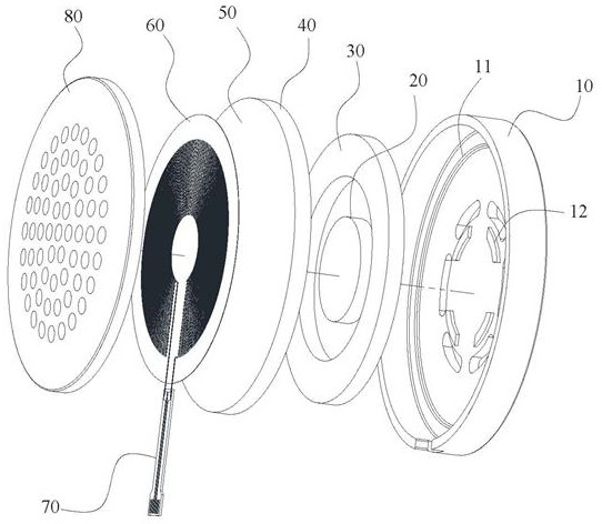
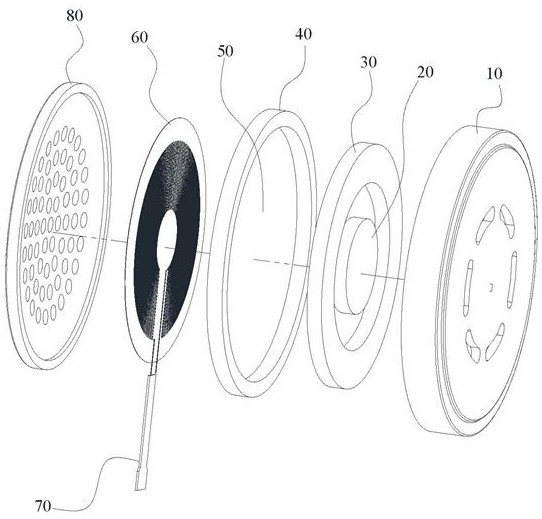
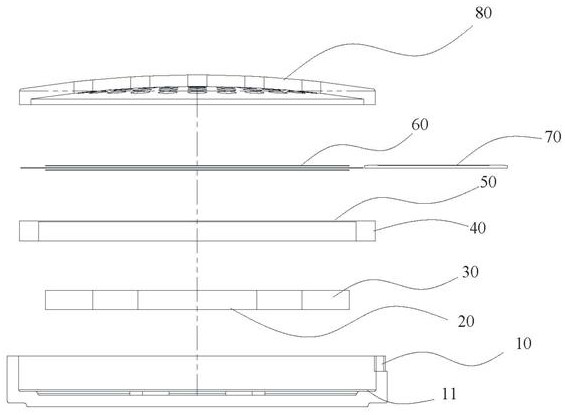
[0044] The following will clearly and completely describe the technical solutions in the embodiments of the present invention with reference to the accompanying drawings in the embodiments of the present invention. Obviously, the described embodiments are only some, not all, embodiments of the present invention.

[0045] It should be noted that when an element is referred to as being "fixed" to another element, it can be directly on the other element or there may be an intervening element. When an element is said to be "connected" to another element, it can be directly connected to the other element or intervening elements may also be present. The terms "vertical," "horizontal," "left," "right," and similar expressions are used herein for purposes of illustration only and are not intended to represent exclusive embodiments.

[0046] Unless otherwise defined, all technical and scientific terms used herein have the same meaning as commonly understood by one of ordinary skill in ...


PUM


Abstract

The invention relates to the technical field of receivers, in particular to a printed coil, a manufacturing method thereof and an earphone receiver. The manufacturing method of the printed coil comprises the following steps: preparing UV ink; preparing a voice coil base material according to a preset shape; printing the prepared UV ink on the voice coil base material according to a preset line; and irradiating the surface of the printed substrate by using a cold light source curing machine to cure and mold the printed circuit. The invention also requests to protect the printed voice coil manufactured by the method and the earphone receiver with the printed voice coil. The coil is printed on the base material through a low-temperature printing method, so that the influence of temperature onthe material is reduced, and the low-frequency sound effect of the product can be better by using TPU; and the upper loop and the lower loop are conducted through the blind holes, so that the occupied space of the base material is further saved, and the overall height of the receiver is reduced.

Description

technical field [0001] The invention relates to the technical field of receivers, in particular to a printed coil, a manufacturing method thereof, and an earphone receiver. Background technique [0002] The receiver is also called the handset, and the English is Receiver. It is an electroacoustic device that converts audio electrical signals into sound signals without sound leakage. It is widely used in communication terminal equipment such as mobile phones, fixed phones, and hearing aids to realize audio playback functions. With the development of thinner and lighter communication terminal equipment, the size and sound effect of the receiver are also getting more and more attention. [0003] In the prior art, conventional earphone receivers are traditional dynamic receivers. Although the sound effect of traditional dynamic receivers is relatively good, in order to improve the low-frequency effect, the selected diaphragms are relatively thin, which is limited by the rigidit...

Claims


Application Information

Patent Timeline
Patent Type & Authority Patents(China)
IPC IPC(8): H04R31/00H04R9/04H04R9/10
CPCH04R9/046H04R9/10H04R31/00
Inventor 王平陶文俊鲍晨凯
Owner BESTAR HLDG
Why Eureka
Try Eureka