
Uplink data transmission method, terminal and communication system

A data transmission method and terminal technology, applied in the field of communication, can solve the problems of reducing voice services, unable to guarantee fast transmission of delay-sensitive services, unable to guarantee fast transmission of group voice services, etc.

Active Publication Date: 2013-09-11
TD TECH COMM TECH LTD
View PDF3 Cites 33 Cited by
  • Summary
  • Abstract
  • Description
  • Claims
  • Application Information

AI Technical Summary

Problems solved by technology

[0005] However, in the LTE system, after the terminal obtains the semi-persistent scheduling authorization signaling carrying the allocation of physical resources issued by the network side, various service data in the terminal can share the physical resources, and the terminal is allocated according to the priority of the logical channel. The data transmission of the group service is performed on the allocated physical resources, that is, the terminal does not give priority to the transmission of the service data corresponding to the semi-persistent scheduling
For example, for the group voice service in the LTE system, when the priority of the logical channel corresponding to other service data in the terminal is higher than the priority of the logical channel corresponding to the voice service, since the terminal performs data transmission according to the priority of the logical channel, Therefore, the service data with high priority is sent through the resources allocated by the network side, and the voice data is sent when there are remaining resources, so that even if the network side uses semi-static scheduling authorization to reduce the delay of voice services, it still cannot guarantee group Fast Transmission of Voice Services
It can be seen that the terminal does not completely transmit the corresponding uplink service data according to the authorized scheduling on the network side, resulting in the inability to guarantee the fast transmission of delay-sensitive services

Method used


Image

  • Uplink data transmission method, terminal and communication system
  • Uplink data transmission method, terminal and communication system
  • Uplink data transmission method, terminal and communication system

Examples


Embodiment 1

[0029] The uplink data transmission method in Embodiment 1 of the present invention consists of figure 1 in the terminal to execute. The uplink data transmission method in Embodiment 1 of the present invention will be described in detail below from the perspective of a terminal.

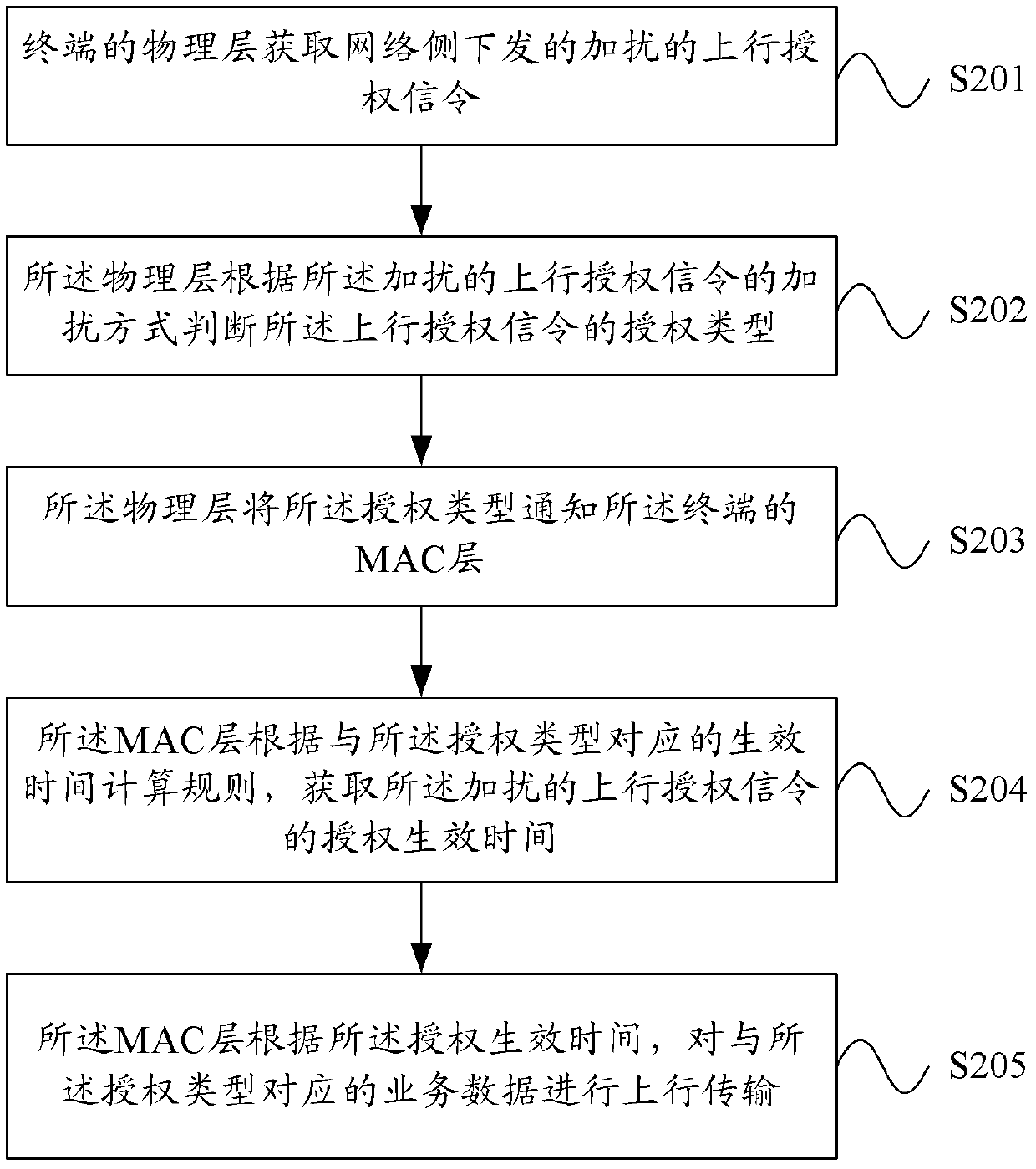
[0030] figure 2 It is a flowchart of an uplink data transmission method according to an embodiment of the present invention. Such as figure 2 As shown, the uplink data transmission method includes the following steps:

[0031] Step S201, the physical layer of the terminal obtains the scrambled uplink authorization signaling issued by the network side;

[0032] Step S202, the physical layer judges the grant type of the uplink grant signaling according to the scrambling mode of the scrambled uplink grant signaling;

[0033] Step S203, the physical layer notifies the MAC layer of the terminal of the authorization type;

[0034] Step S204, the MAC layer obtains the authorization effective time of...


PUM


Abstract

The invention provides an uplink data transmission method, terminal and communication system. The method comprises the steps that a physical layer of the terminal obtains a scrambling uplink authorization signal issued by a network side; the physical layer judges the authorization type of the uplink authorization signal according to the scrambling mode of the uplink authorization signal; the physical layer sends the authorization type to a medium accessing control (MAC) layer of the terminal; the MAC layer obtains authorization entry-into-force time of the uplink authorization signal according to an entry-into-force time computing rule corresponding to the authorization type; the MAC layer carries out uplink transmission on service data corresponding to the authorization type according to the authorization entry-into-force time.

Description

technical field [0001] The invention relates to cluster technology, in particular to an uplink data transmission method, a terminal and a communication system, and belongs to the technical field of communication. Background technique [0002] With the rapid increase of users' demand for data services, the wireless communication system has been developed from the third generation mobile communication system to the Long Term Evolution (LTE) system. [0003] In the group voice service of the LTE system, a group has a speaker user and multiple monitor users. When the speaker user is speaking, other monitor users are listening. That is to say, the uplink data transmission of the speaker user affects the entire group. The receiving delay of all listening users. The group voice service has strict requirements on delay, and it is hoped that when there is data in the buffer, there will be available resources to send the data packet to the base station as soon as possible. [0004] ...

Claims


Application Information

Patent Timeline
Patent Type & Authority Applications(China)
IPC IPC(8): H04W72/12H04W88/02
Inventor 袁菁王健
Owner TD TECH COMM TECH LTD
Learn More