
Floor

A floor and hollow board technology, applied in the floor field, can solve problems such as the influence of other equipment, the layout of humidifiers and dehumidifiers, etc.

Active Publication Date: 2013-09-18
SUGON DATAENERGYBEIJING CO LTD
View PDF6 Cites 4 Cited by
  • Summary
  • Abstract
  • Description
  • Claims
  • Application Information

AI Technical Summary

Problems solved by technology

[0002] At present, most of the computer room humidification and dehumidification products used in the industry are separate products, which are independently installed in a certain area of ​​the computer room. When the space in the computer room is limited, the layout of the humidifier and dehumidifier is more difficult to solve
And once the humidifier leaks, it will also affect other equipment

Method used


Image

  • Floor

Examples


Embodiment Construction

[0016] Specific embodiments of the present invention will be described below in conjunction with the accompanying drawings.

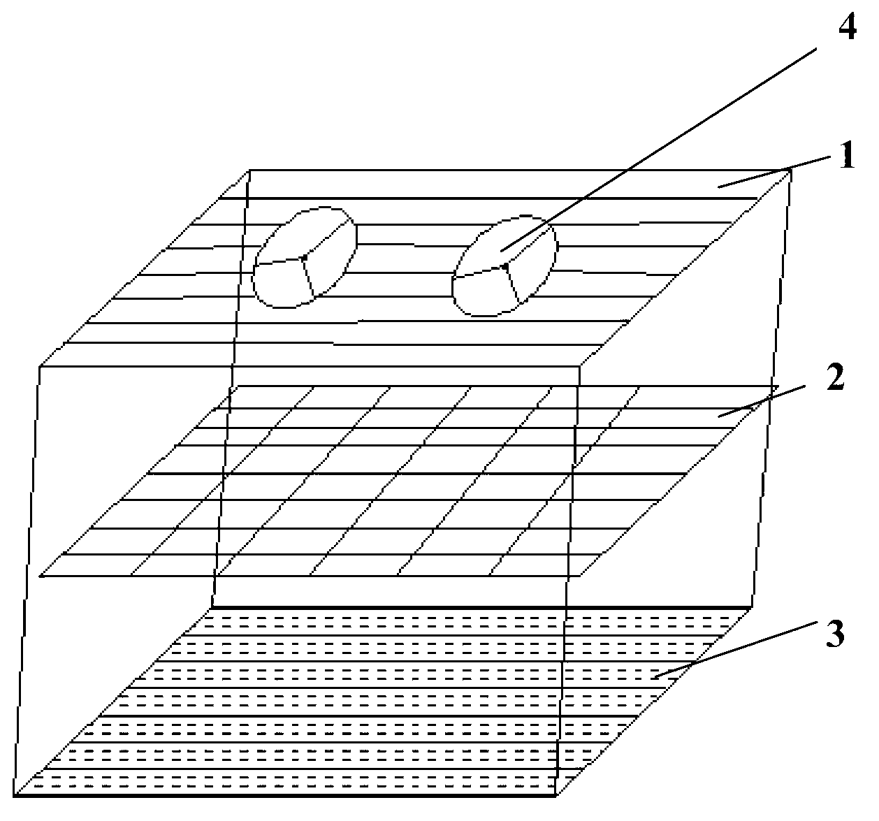
[0017] see figure 1 , the floor covering surface layer 1, the humidifying layer 2 and the dehumidifying layer 3 of the present invention. Wherein, the surface layer 1 has a plurality of fans 4 . The humidifying layer 2 and the dehumidifying layer 3 are arranged below the surface layer 1 and are separated from each other along a direction perpendicular to the surface layer 1 . Moreover, both the humidifying layer 2 and the dehumidifying layer 3 are on the blowing path of the fan 4 of the surface layer 1 . It should be understood that the fan 4 used in the floor surface 1 of the present invention can rotate clockwise or counterclockwise. Take the fan 4 rotating clockwise and the wind blowing from the outside of the surface layer 1 into the inside of the surface layer 1 as an example (the rotation direction of the fan and the direction of blowing air ar...


PUM


Abstract

A floor comprises a surface layer (1), a humidification layer (2) and a dehumidification (3), wherein the surface layer (1) comprises a plurality of fans (4); and the humidification layer (2) and the dehumidification (3) are arranged below the surface layer (1) respectively, spaced in the direction perpendicular to the surface layer, and arranged on the blowing path of the fans (4). According to the floor, indoor humidity can be regulated; and as the humidification layer is arranged below the surface layer of the floor, water leakage cannot affect indoor equipment.

Description

technical field [0001] The present invention relates to a floor. Background technique [0002] At present, most of the computer room humidification and dehumidification products used in the industry are separate products, which are independently installed in a certain area in the computer room. When the space in the computer room is limited, the layout of the humidifier and dehumidifier is more difficult to solve. And once the humidifier leaks, it will also affect other equipment. Contents of the invention [0003] In view of one or more problems in the related art, the object of the present invention is to provide a floor that can adjust indoor humidity. [0004] In order to achieve the above object, a floor is provided, comprising: a surface layer with a plurality of fans; and a humidification layer and a dehumidification layer respectively arranged below the surface layer and separated from each other along a direction perpendicular to the surface layer, wherein, The ...

Claims


Application Information

Patent Timeline
Patent Type & Authority Applications(China)
IPC IPC(8): E04F15/024
Inventor 刘广辉邵宗有沈卫东李宝雨刘金星
Owner SUGON DATAENERGYBEIJING CO LTD
Learn More