Flow restricting ring

A current-limiting ring and current-limiting technology, which is applied in the field of current-limiting rings, can solve the problem that the current-limiting ring does not meet the requirements, the elastic deformation is easily affected by the external temperature, the temperature of the fluid, the pressure of the fluid, and the error of the current-limiting ring Large and other problems, to achieve the effect of good current limiting effect, uniform force, and improved current limiting effect

Active Publication Date: 2013-09-18
珠海维家热能科技有限公司
View PDF5 Cites 7 Cited by
  • Summary
  • Abstract
  • Description
  • Claims
  • Application Information

AI Technical Summary

Problems solved by technology

At present, a Chinese patent with a publication number of 202852312U discloses a current limiting ring, which includes a current limiting ring body. The center of the current limiting ring body is provided with an integrated thin-walled ring. There is a flow hole between them, and the outer circumference of the thin-walled ring is sleeved with a current-limiting rubber ring. The current-limiting rubber ring is an important component in the current-limiting ring and plays an important role in limiting the current. Made of rubber, the elastic deformation of rubber is easily affected by the temperature of the outside world, the temperature of the fluid, and the pressure of the fluid. When used in winter, the flow limit may reach 12L±10%, and vice versa, the error may be ±20%, and the error may reach ±30% in severe cases. In some places with high flow limit requirements, due to this The error of the current limiting ring is large, so the current limiting ring often fails to meet the requirements, so it is necessary to improve the existing defects

Method used


Image

  • Flow restricting ring
  • Flow restricting ring
  • Flow restricting ring

Examples


Embodiment Construction

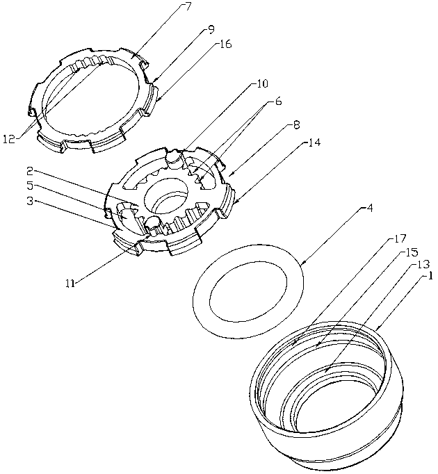
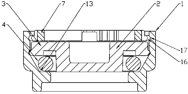
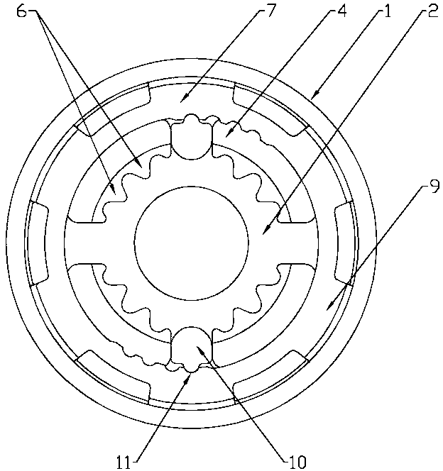
[0016] Such as Figure 1 to Figure 3 As shown, in this embodiment, the present invention includes a ring body 1, a current limiting column 2 arranged in the ring body 1, sleeved in the ring body 1 and fixedly connected to the current limiting column 2. An annular support 3 and a restrictor rubber ring 4 sleeved on the restrictor column 2, a restrictor hole 5 is provided between the restrictor column 2 and the annular support 3, and the outer circumference of the restrictor column 2 is provided There is an overflow groove 6, the direction of the overflow groove 6 is the same as the direction of fluid flow, an adjustment ring 7 is coaxially arranged above the annular bracket 3, and a plurality of adjustment grooves 8 are arranged on the outer periphery of the annular bracket 3, The outer circumference of the adjusting ring 7 is provided with adjusting protrusions 9 that are adapted to the plurality of adjusting grooves 8. When it is found that a large error of the current limitin...


PUM


Abstract

The invention discloses a flow restricting ring, which is simple in structure, good in flow restricting effect and can be adjustable. The flow restricting ring comprises a ring body (1), a flow restricting pillar (2), a ring-shaped bracket (3) sleeved in the ring body (1) and fixedly connected with the flow restricting pillar (2), and a flow restricting rubber ring (4) sleeved on the flow restricting pillar (2), wherein a flow restricting hole (5) is formed between the flow restricting pillar (2) and the ring-shaped bracket (3); an overflow groove (6) is formed at the circumference of the flow restricting pillar (4); an adjusting ring (7) is coaxially arranged above the ring-shaped bracket (3); a plurality of adjusting grooves (8) are formed at the circumference of the ring-shaped bracket (3); and adjusting bulges (9) matched with the adjusting grooves (8) are arranged at the circumference of the adjusting ring (7). The flow restricting ring can be applied to the technical field of wall-mounted furnaces, water heaters and other pipeline equipment.

Description

Technical field [0001] The present invention relates to a current-limiting ring, in particular to a current-limiting ring capable of fine-tuning and limiting flow. Background technique [0002] The restrictor ring is an important part of equipment such as valves, pipes, and water heaters. It is used to restrict the flow of fluid to obtain a predetermined flow rate, and protect the valve, pipe, water heater and other equipment, and can also stabilize the fluid The function of data, as far as wall-hung boilers and water heaters are concerned, flow-limiting rings are often used to limit the size of the flow, and the water flow is automatically adjusted according to changes in water pressure to achieve the purpose of constant temperature. At present, there is a Chinese patent with publication number 202852312U that discloses a restrictor ring, which includes a restrictor ring body. The center of the restrictor ring body is provided with an integrated thin-walled ring. The thin-walled...

Claims


Application Information

Patent Timeline
Patent Type & Authority Applications(China)
IPC IPC(8): F16L55/027
Inventor 王勇林颋郭建恒
Owner 珠海维家热能科技有限公司
Why Eureka
Try Eureka