Multifunctional flood drainage system

A multi-functional, water inlet technology that can be used in waterway systems, sewage removal, drainage structures, etc., and can solve problems such as floods

Pending Publication Date: 2021-06-25
成都市陈式船舶研发有限公司
View PDF0 Cites 0 Cited by
  • Summary
  • Abstract
  • Description
  • Claims
  • Application Information

AI Technical Summary

Problems solved by technology

[0005] The purpose of the present invention is: in order to solve the problems of floods and drainage in daily life, the present invention provides a multifunctional flood drainage system

Method used


Image

  • Multifunctional flood drainage system
  • Multifunctional flood drainage system
  • Multifunctional flood drainage system

Examples


Embodiment 1

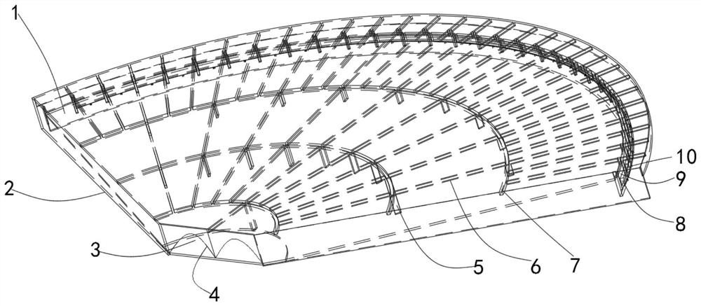
[0033] Such as figure 1 , 5, 6, the present embodiment provides a multifunctional flood drainage system, including a water inlet device 101, an underground pipe 102 and a water outlet device 103, and the two ends of the underground pipe 102 are respectively connected to the water inlet device 101 and the water outlet device 102, so The water inlet device 101 is arranged on the bank of the river and close to the river bank wall. The water inlet device 101 has a top plate 1, a bottom plate 2, a support column 5 and a water inlet 9 (flat shape), and the top plate 1 has a transverse reinforcing rib 7 and longitudinal ribs 6, the top of the support column 5 connects the transverse ribs 7 and the longitudinal ribs 6 on the top plate 1, the top plate 1, the bottom plate 2, the support columns 5, the transverse ribs 7 and the longitudinal ribs 6 forms a chamber, the bottom is connected to the bottom plate 2, the top plate 1 is parallel to the horizontal plane, the water inlet device ...

Embodiment 2

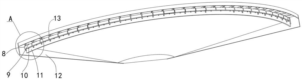
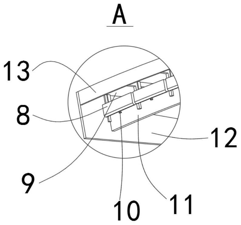
[0039] Working principle: the clapboard 12 and the edge 13 are buried in the river sand, when the river bed reaches the warning water level in the flood season, the float 10 pushes the buoy box 8 to move upward (the float 10 floats up naturally, sealing the telescopic connection between the float 10 and the buoy box 8 The exhaust hole around the shaft, the floating tank 8 also keeps empty and floats up), when the floating tank 8 completely covered the water inlet 9, when the floating tank 8 was filled with water, the floating tank 8 sank, because the water inlet 9 was separated from the edge 13 4m, the water around the water inlet 9 reaches the full-load water intake state, and then according to the drop between the water inlet part and the water outlet part in the range of 3.5-4m or the height of the water inlet 9 is 1m to make the flat water inlet 9 to the water outlet 4 The short distance and large drop also promote the quick start of the system, and the flow rate or flow in...

Embodiment 3

[0041] Application 1: When the Jintang river bed reaches the warning water level during the flood season, the drainage level of the matching embankment at the water inlet 9 of the system is raised to the highest point of the water inlet 9 of the system, and the water inlet does not need any control, and it is close to the sealed floating tank 8 and the float 10. At a uniform height, water enters the relatively static space at the same time. The buoyant tank 8 is filled with water and sinks instantly, so that the water inlet 9 is saturated with water, and the full load is reached in about 20 minutes. The water level of the river bed above the embankment drops by one meter. , the effect of incoming water under the water surface of the water inlet 9 maintains the full load effect equally.

[0042] Application 2: In most of the idle time when there is no flood discharge, connect the tunnel or driveway 104 between the two ends of the water inlet device 101 and the water outlet devic...


PUM


Abstract

The invention discloses a multifunctional flood drainage system and relates to the technical field of urban drainage waterlogging prevention and rainwater resource utilization. The multifunctional flood drainage system solves the technical problem of flood drainage. The multifunctional flood drainage system involves a water inlet device, an underground pipe and a water outlet device, wherein the two ends of the underground pipe are connected with the water inlet device and the water outlet device correspondingly, the water inlet device is provided with a top plate, a bottom plate and a supporting column, transverse reinforcing ribs and longitudinal reinforcing ribs are arranged on the top plate, the upper portion of the supporting column is connected with the transverse reinforcing ribs and the longitudinal reinforcing ribs on the top plate, the top plate, the bottom plate, the supporting column, the transverse reinforcing ribs and the longitudinal reinforcing ribs form a cavity, the lower portion of the supporting column is connected with the bottom plate, the top plate is parallel to the horizontal plane, the water inlet device is provided with a water inlet part and a water outlet part, the water inlet part communicates with the water outlet part through the cavity, the water inlet part is higher than the water outlet part, and the difference between the water inlet part and the water outlet part is 3.5-4m. The multifunctional flood drainage system is used for timely draining river water and reducing the water level height of the river water, and has the advantages of siphoning type drainage and large-area and large-flow drainage.

Description

technical field [0001] The present invention relates to the technical field of urban drainage and waterlogging prevention and utilization of rainwater resources, and more specifically relates to a multifunctional flood drainage system, which is used to discharge the river water in time when the water level of the river in the annual flood disaster rises and exceeds the water level line, so as to reduce the water consumption of the river. water level. Background technique [0002] Due to the limitation of urban land resources, it is becoming more and more difficult to use low-lying land, ponds, lakes, reservoirs, etc. on the ground to store rainwater. In order to resolve the waterlogging risk, on the basis of the existing urban drainage pipe network system, increasing the underground water storage space is one of the main methods to solve the waterlogging problem. The expansion of the volume makes it an independent storage tank. The storage tank has a certain effect on colle...

Claims


Application Information

Patent Timeline
Patent Type & Authority Applications(China)
IPC IPC(8): E03F1/00E03F5/20
CPCE03F1/00E03F5/20
Inventor 陈良奎
Owner 成都市陈式船舶研发有限公司
Why Eureka
Try Eureka