Image display device and image display method
一种图像显示装置、显示部的技术,应用在静态指示器、仪器等方向,能够解决场序彩色方式色乱等问题
- Summary
- Abstract
- Description
- Claims
- Application Information
AI Technical Summary
Problems solved by technology
Method used
Image
Examples
no. 1 Embodiment approach >
[0103]
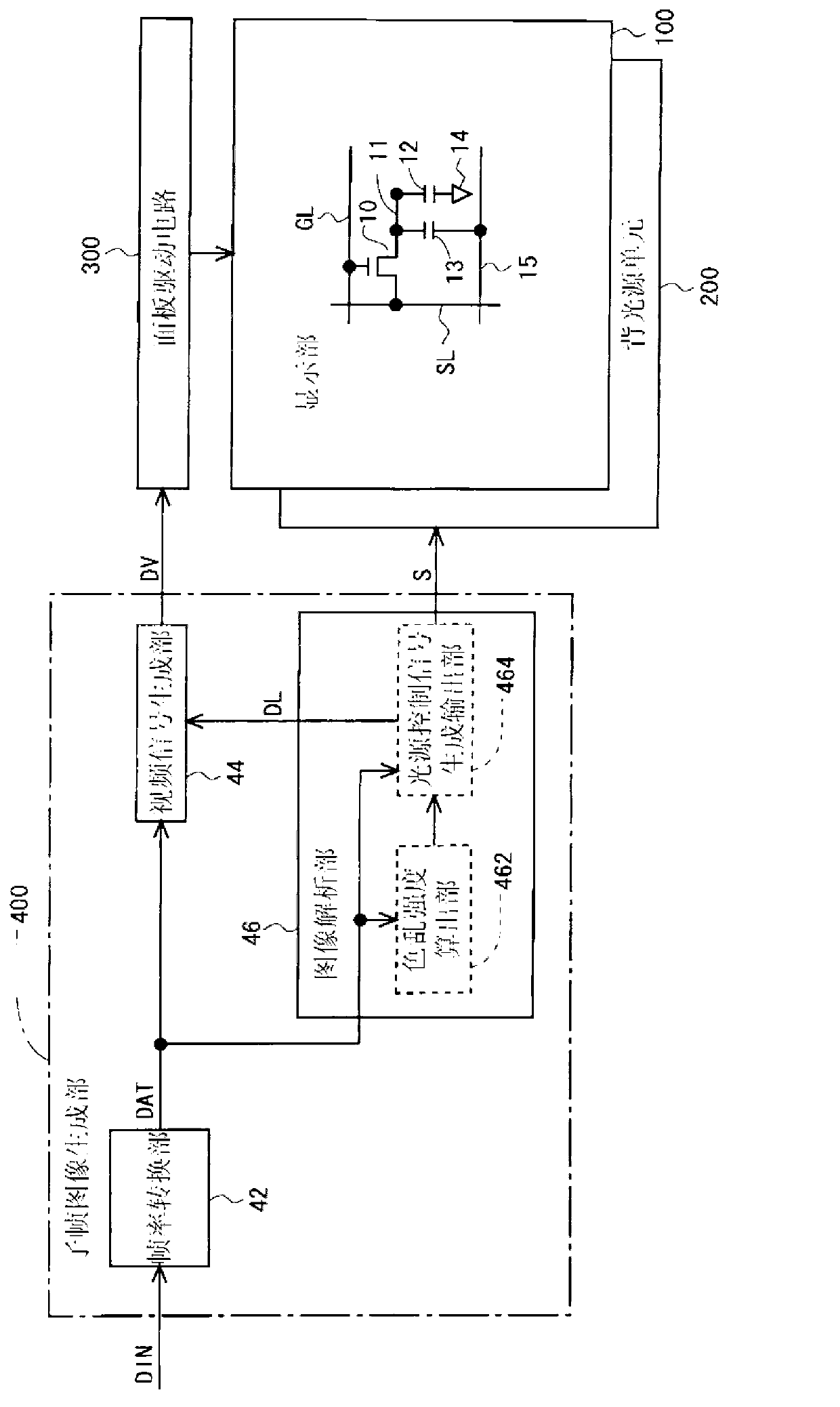
[0104] figure 1 It is a block diagram showing the overall configuration of the liquid crystal display device according to the first embodiment of the present invention. This liquid crystal display device includes a display unit 100 , a backlight unit 200 , a panel drive circuit 300 and a sub-frame image generation unit 400 . The sub-frame image generation unit 400 includes a frame rate conversion unit 42 , a video signal generation unit 44 , and an image analysis unit 46 . The image analysis unit 46 includes a color breakup intensity calculation unit 462 and a light source control signal generation output unit (light source control unit) 464 . The backlight unit 200 includes LEDs of three colors, red (R), green (G), and blue (B), as a backlight (light source unit), and a program that controls the states (on state / off state) of these LEDs. LED control circuit. In addition, generally, a plurality of LEDs of each color are provided.
[0105] A plurality of source ...
no. 2 Embodiment approach >
[0160]
[0161] The configuration of the liquid crystal display device and the configuration of one frame period are the same as those of the above-mentioned first embodiment, so descriptions thereof are omitted (see figure 1 and figure 2 ). In addition, the calculation method of the first pixel area, the calculation method of the second pixel area, and the calculation method of the color break-up intensity are the same as those of the above-mentioned first embodiment, so description thereof will be omitted.
[0162] In the present embodiment, the light source control signal generating and outputting unit 464 operates as Such as Figure 20 As shown, the light source control signal S is output so that the LEDs of all colors are turned off in the extended subframe.
[0163]
[0164] According to the present embodiment, when displaying an image whose color breakup is difficult to be visually recognized, all the LEDs are turned off in the extended subframe. Therefore, th...
no. 3 Embodiment approach >
[0170]
[0171] In each of the above embodiments, only one extended subframe is provided in one frame period. However, depending on the target image, it is considered that visual recognition of multiple mixed color components may be disturbed. For example, sometimes Figure 22 As shown, in the target image, there are a region Z1a containing many yellow components and a region Z1b containing many cyan components. In such a case, even if yellow display is performed in (only one of which is provided in one frame period), color breakup due to the cyan component occurs. Therefore, in this embodiment, if Figure 23 As shown in , there are two extended subframes (the first extended subframe and the second extended subframe) in one frame period. In addition, since the configuration of the liquid crystal display device is the same as that of the above-mentioned first embodiment, description thereof will be omitted (see figure 1 ).
[0172]
[0173] How to set the states of th...
PUM
 Abstract
Description
Claims
Application Information
 - R&D
- Intellectual Property
- Life Sciences
- Materials
- Tech Scout
- Unparalleled Data Quality
- Higher Quality Content
- 60% Fewer Hallucinations
Browse by: Latest US Patents, China's latest patents, Technical Efficacy Thesaurus, Application Domain, Technology Topic, Popular Technical Reports.
© 2025 PatSnap. All rights reserved.Legal|Privacy policy|Modern Slavery Act Transparency Statement|Sitemap|About US| Contact US: help@patsnap.com


