Large-handling-capacity photocatalytic wastewater degradation reactor for preventing water inrush of placement cavity of light source

A waste water degradation and treatment capacity technology, applied in water/sewage multi-stage treatment, water/sludge/sewage treatment, chemical instruments and methods, etc., can solve problems such as easy to pollute the inner wall of the quartz tube

Active Publication Date: 2013-09-25
重庆尧群环保科技有限公司
View PDF4 Cites 2 Cited by
  • Summary
  • Abstract
  • Description
  • Claims
  • Application Information

AI Technical Summary

Problems solved by technology

[0048] Based on the structure of the CN102260003A scheme, the electrodeless ultraviolet lamp is placed in the lumen of the quartz tube. In order to ensure the normal luminous work of the electrodeless ultraviolet lamp, the inner wall of the quartz tube must be kept clean to maintain the permeability to ultraviolet light. Moreover, based on similar light permeability requirements, the outer side of the lamp wall of the electrodeless ultraviolet lamp involved must also be kept clean; however, the structure of the CN102260003A scheme is difficult to avoid the problem of water inrush in the lumen area of ​​the quartz tube The so-called water inrush in this case refers to the unwelcome water in the reactor protruding into the lumen area of ​​the quartz tube; there are generally two reasons for the water inrush: one is the quartz tube The thermal expansion and contraction of the air in the cavity area leads to underpressure in the lumen area of ​​the quartz tube, and the second is that the air in the lumen area of ​​the quartz tube escapes and causes underpressure in the lumen area of ​​the quartz tube. In this way, driven by the relative positive pressure of the surrounding water body, The water in the reactor

Method used


Image

  • Large-handling-capacity photocatalytic wastewater degradation reactor for preventing water inrush of placement cavity of light source
  • Large-handling-capacity photocatalytic wastewater degradation reactor for preventing water inrush of placement cavity of light source

Examples


Embodiment Construction

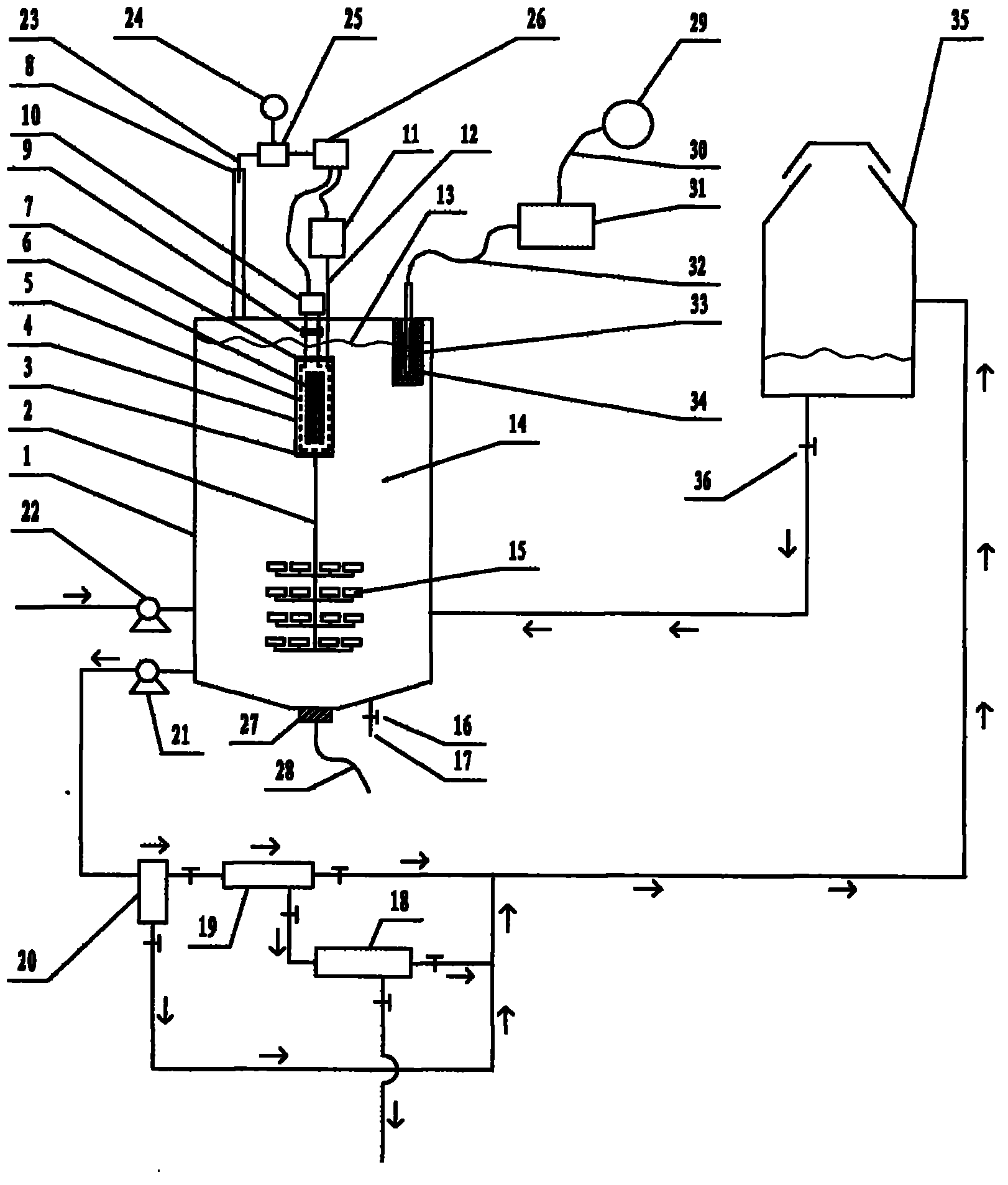
[0129] exist figure 1In the shown embodiment of the present case, the structure of the reactor includes a container 1, and the outline of the container 1 is in the shape of a cube, a cuboid, a cylinder, an ellipse, a polygon, a sphere or an ellipsoid, Many microporous aeration heads 15 are installed in the lower area of ​​the inner cavity of the container 1, and the label 15 only indicates the microporous aeration head individuality and its shape, and the quartz tube 4, which is erected on the The position of the inner chamber of the container 1, the two ends of the quartz tube 4 are equipped with plugging caps 3,7, and the plugging caps 3,7 located at the two ends of the quartz tube are respectively provided with ventilation ports, and the electrodeless ultraviolet Lamp 6, the electrodeless ultraviolet lamp 6 is rod-shaped, ring-shaped, spherical, starfish-shaped or sea urchin-shaped, the number of the electrodeless ultraviolet lamp 6 is at least one, and the electrodeless ul...


PUM


Abstract

The invention relates to a large-handling-capacity photocatalytic wastewater degradation reactor for preventing water inrush of a placement cavity of a light source and belongs to the technical field of wastewater treatment. The reactor is used for solving the problems in prior art that water suddenly flows into a tube cavity of a quartz tube for shielding an electrodeless lamp, the microwave energy is wasted, the wastewater handling capacity of a single tank is relatively low, an interception link of accelerant particles is relatively weak, a degradation reaction endpoint time is difficult to distinguish, accelerant aggregates cannot be strongly dissipated in situ, accelerant aggregation cannot be immediately noticed and secondary ozone reversely flows to erode a magnetic control pipe. Aiming at the problems, according to the scheme, a miniature membrane pump capable of normally working in a low-power-consumption manner is connected to a linking gas circuit between an air pump and the tube cavity of the quartz tube in a bypass manner and can supplement continuous low-flow air to the tube cavity of the quartz tube so as to repress water inrush of the tube cavity of the quartz tube; microwaves are restricted by a metal cage, and the large volume expansion of the reactor is allowed due to the structure of metal cage; and by utilizing the structure, all other problems are solved once.

Description

technical field [0001] The invention relates to a large-capacity photocatalytic wastewater degradation reactor for preventing water inrush from a light source installation cavity, and belongs to the technical field of CO2F wastewater treatment. Background technique [0002] Microwave photocatalytic degradation treatment technology, as an effective harmless treatment technology for industrial wastewater containing organic pollutants, has attracted much attention in recent years. [0003] Regarding the microwave photocatalytic degradation technology, as an example, refer to the Chinese patent application with publication number CN102260003A. [0004] The Chinese patent application with the publication number CN102260003A uses microwaves as the excitation source to excite the electrodeless ultraviolet lamp to emit ultraviolet rays, and irradiates the suspension mixed with photocatalyst titanium dioxide inside the liquid. The electrodeless ultraviolet lamp is shrouded and protec...

Claims


Application Information

Patent Timeline
IPC IPC(8): C02F9/08
Inventor 李榕生
Owner 重庆尧群环保科技有限公司
Why Eureka
Try Eureka