Lifting device

A technology of lifting device and deceleration device, applied in the field of lifting system, to achieve the effect of improving lifting capacity, meeting restrictions, reasonable and compact structure

Active Publication Date: 2015-01-28
SICHUAN HONGHUA PETROLEUM EQUIP
View PDF7 Cites 0 Cited by
  • Summary
  • Abstract
  • Description
  • Claims
  • Application Information

AI Technical Summary

Problems solved by technology

Each lifting system contains four sets of lifting devices. The layout of the lifting devices in the pile box is a key issue for designers to consider. The quality of the layout directly affects the lifting capacity and safety performance of the lifting system, but in reality it is limited by space, weight, etc. Due to the limitation of conditions, how to optimize the layout has become a problem that has plagued designers for a long time

Method used


Image

  • Lifting device
  • Lifting device
  • Lifting device

Examples


Embodiment 1

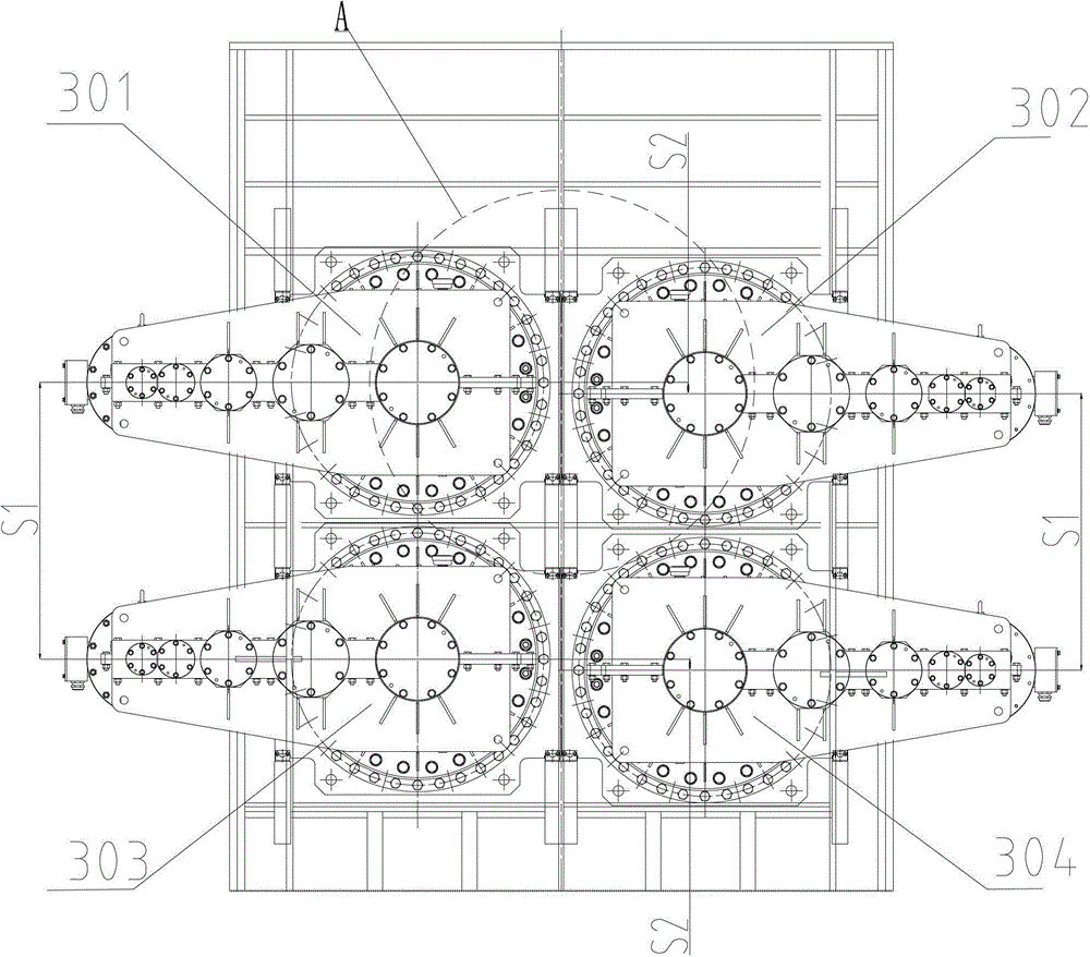
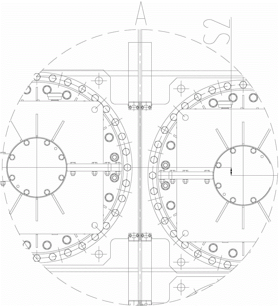
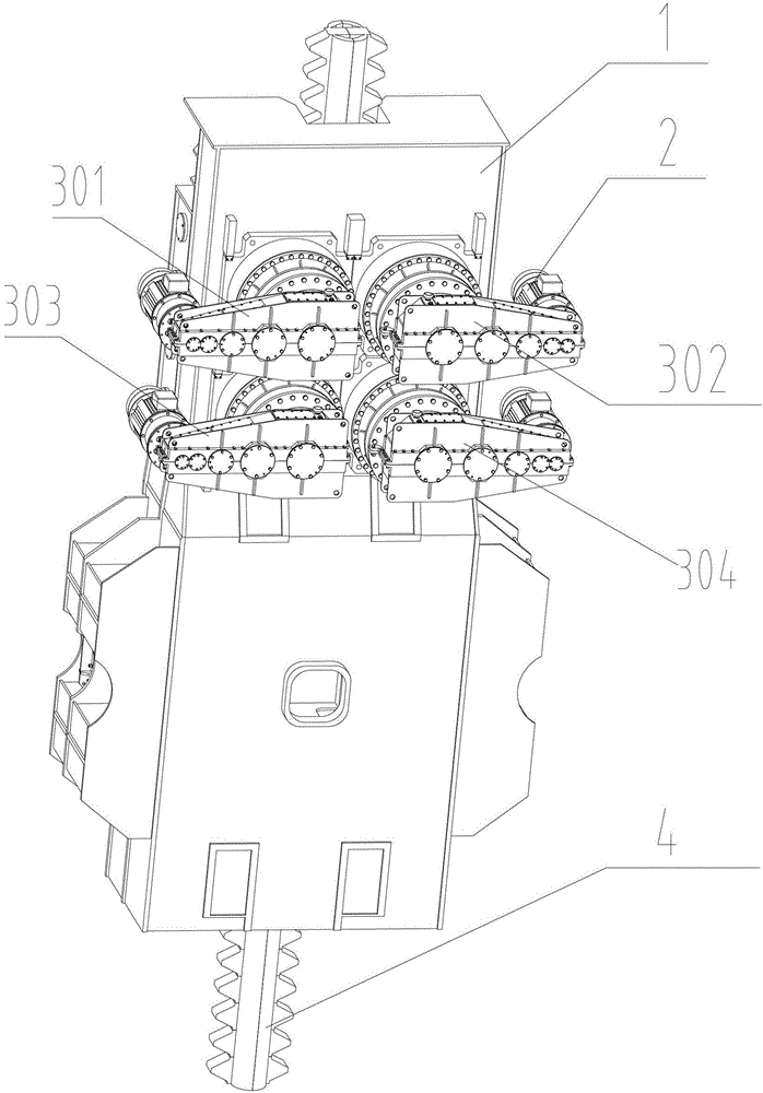
[0017] The lifting platform is a mobile offshore engineering platform used for offshore energy exploration and exploration. Its main components are the working platform, the legs supporting the platform, and the lifting system that controls the lifting of the working platform. The lifting system is mainly composed of motor, reduction device, main lifting gear shaft assembly and so on. Such as image 3 The three-dimensional structure diagram of a lifting device shown, the leg rack 4 and the lifting gear are arranged inside the pile box 1, the first reduction device 301, the second reduction device 302, the third reduction device 303 and the fourth reduction device 304 are arranged on the side of the pile box 1, and the tooth pitch of the leg rack 4 is mπ, where m represents the modulus of the leg rack. The four motors 2 are respectively connected to the input shafts of the first deceleration device 301, the second deceleration device 302, the third deceleration device 303 and ...


PUM


Abstract

The invention relates to a lifting system of a self elevating platform, in particular to a lifting device. The lifting device comprises a pile leg rack, a lifting gear and a reduction gear, wherein the reduction gear is connected with the pile leg rack through the lifting gear, the tooth pitch of the pile leg rack is m pi, and the reduction gear comprises a first reduction gear body, a second reduction gear body, a third reduction gear body and a fourth reduction gear body. The vertical distance between the axis of the output shaft of the first reduction gear body and the axis of the output shaft of the third reduction gear body can be described as S1=(2N-1)K1m pi / 2, wherein N is a natural number, and K1 is between 0.8 to 1. The vertical distance between the axis of the output shaft of the first reduction gear body and the axis of the output shaft of the second reduction gear body can be described as S2=K2m pi / 4, wherein K2 is between 0.7 to 1. According to the lifting device, the lifting capacity of the system is fully utilized, and the safety performance of the whole lifting system is improved.

Description

technical field [0001] The invention relates to a lifting system of a lifting platform, in particular to a lifting device. Background technique [0002] The lifting platform is a mobile offshore engineering platform used for offshore energy exploitation and exploration. Its main components are the working platform, the legs supporting the platform, the lifting system that controls the lifting of the working platform and the locking system after the working platform is positioned. . Among them, both the lifting system and the locking system are installed inside the pile box, and the locking system is arranged under the lifting system, and they become a whole through the pile box and the platform. Each lifting system contains four sets of lifting devices. The layout of the lifting devices in the pile box is a key issue for designers to consider. The quality of the layout directly affects the lifting capacity and safety performance of the lifting system, but in reality it is l...

Claims


Application Information

Patent Timeline
Patent Type & Authority Patents(China)
IPC IPC(8): E02B17/08
CPCE02B17/021E02B17/0872
Inventor 吴勇雍军袁霄
Owner SICHUAN HONGHUA PETROLEUM EQUIP
Why Eureka
Try Eureka