Manual louver valve

A louver valve and valve body technology, applied in the direction of lift valve, valve details, valve device, etc., can solve problems such as unreasonable design and defective details, and achieve the effect of reasonable design, small flow resistance, and small opening and closing torque.

Inactive Publication Date: 2013-10-02
NANTONG XUYANG MACHINERY MFG
View PDF7 Cites 4 Cited by
  • Summary
  • Abstract
  • Description
  • Claims
  • Application Information

AI Technical Summary

Problems solved by technology

However, due to the unreasonable design of the existing manual shutter valves, there are still defects in details, so there is still a need for improvement.

Method used


Image

  • Manual louver valve

Examples


Embodiment Construction

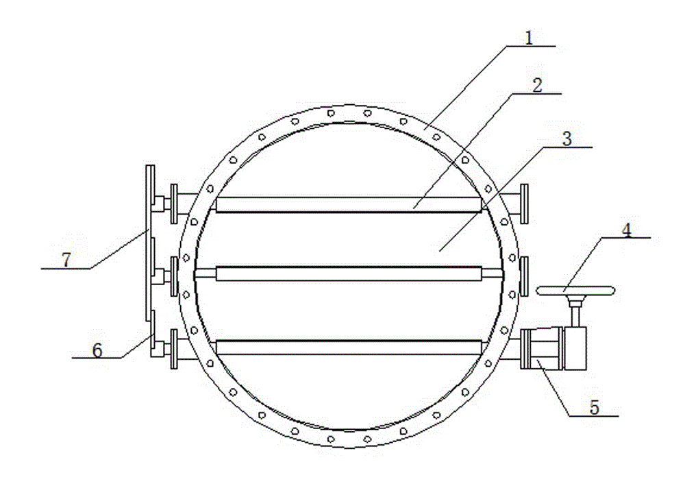
[0010] refer to figure 1 , this specific embodiment adopts the following technical solutions: a manual shutter valve, including a valve body 1, at least one rotatable valve shaft 2 is arranged in the valve body 1, and a valve shaft 2 is fixed on the valve shaft 2. Plate 3, and the valve plate 3 is matched with the valve body 1, so as to ensure good sealing performance when the valve plate 3 is closed; the handwheel 4 is arranged outside the valve body 1, and the valve shaft One end of the valve shaft 2 protrudes from the valve body 1 and is connected to the hand wheel 4 through the crank 5, and the other end of the valve shaft 2 protrudes from the valve body 1 and is connected to one end of the pull rod 6 , the other end of the tie rod 6 is connected to the connecting rod 7. It should be noted that the direction of the respective pull rods 6 corresponding to the valve shaft 2 is set in the same direction, so that the action of the connecting rod 7 drives other valve shafts 2 ...


PUM


Abstract

The invention discloses a manual louver valve which relates to the technical field of valves. The manual louver valve comprises a valve body; at least one rotary valve shaft is arranged in the valve body; a valve plate is fixedly arranged on the valve shaft; the valve plate is matched with the valve body; a hand wheel is arranged outside the valve body; one end of the valve shaft extends out of the valve body, and is connected with the hand wheel through a crank; the other end of the valve shaft extends out of the valve body and is connected with one end of a tension rod; and the other end of the tension rod is connected with a connecting rod. According to the manual louver valve, the design is reasonable, the airflow is uniformlyshunted due to a multi-leaf and multi-shaft design, the flow resistance is small, the opening and closing torque is small, the action is flexible and reasonable, the air volume can be effectively controlled, the energy is fully utilized so that a working system is in the best state, and the valve is ideal airflow regulating equipment in various air duct systems.

Description

technical field [0001] The invention relates to the technical field of valves, in particular to a manual shutter valve. Background technique [0002] At present, the louver valve is mainly used in pipelines, and the air volume can be well controlled through the louver valve. After a long period of development, the existing shutter valve has been widely used in cement, metallurgy, mining and other industrial occasions, and its appearance has solved the need to open and close and effectively control the air volume when the ventilation of each pipeline. However, the existing manual shutter valves still have defects in details due to unreasonable design, so there is still a need for improvement. Contents of the invention [0003] The purpose of the present invention is to provide a manual shutter valve with reasonable design, novel structure and effective control of gas flow. [0004] In order to solve the problems existing in the background technology, the present invention...

Claims


Application Information

Patent Timeline
Patent Type & Authority Applications(China)
IPC IPC(8): F16K1/18F16K1/32F16K27/02
Inventor 唐永年
Owner NANTONG XUYANG MACHINERY MFG
Why Eureka
Try Eureka