Electronically controlled fuel injection valve

A fuel injection valve, electronic control technology, applied in the direction of fuel injection device, charging system, engine components, etc., can solve the problems of needle or valve plate damage, fuel oil leakage to the combustion chamber, etc., to achieve easy processing, opening and closing The effect of increased pressure and easy replacement

Active Publication Date: 2013-10-02
HYUNDAI HEAVY IND CO LTD
View PDF5 Cites 2 Cited by
  • Summary
  • Abstract
  • Description
  • Claims
  • Application Information

AI Technical Summary

Problems solved by technology

[0004] Conventional mechanical fuel injection valves have a structure in which the needle is lifted only by the pressure of the fuel injected into the cavity of the nozzle to inject fuel, and the injection characteristics such as the injection timing and injection amount of the fuel are always fixed, so there is a problem that it cannot The problem of achieving fuel injection control independent of engine operating conditions
[0005] In addition, with conventional electronically controlled fuel injection valves, the fuel supplied to the nozzle portion through the fuel supply port is always supplied to the nozzle portion, so high pressure is always applied to the nozzle portion. When problems such as damage to the nozzle needle or valve plate occur , there is a problem of a large amount of fuel leaking into the combustion chamber

Method used


Image

  • Electronically controlled fuel injection valve
  • Electronically controlled fuel injection valve
  • Electronically controlled fuel injection valve

Examples


Embodiment Construction

[0048] The configuration and function of an embodiment of the present invention will be described in detail below in conjunction with the accompanying drawings. In addition, in describing the present invention, when it is judged that the detailed description of related known functions or configurations may unnecessarily obscure the gist of the present invention, the detailed description will be omitted.

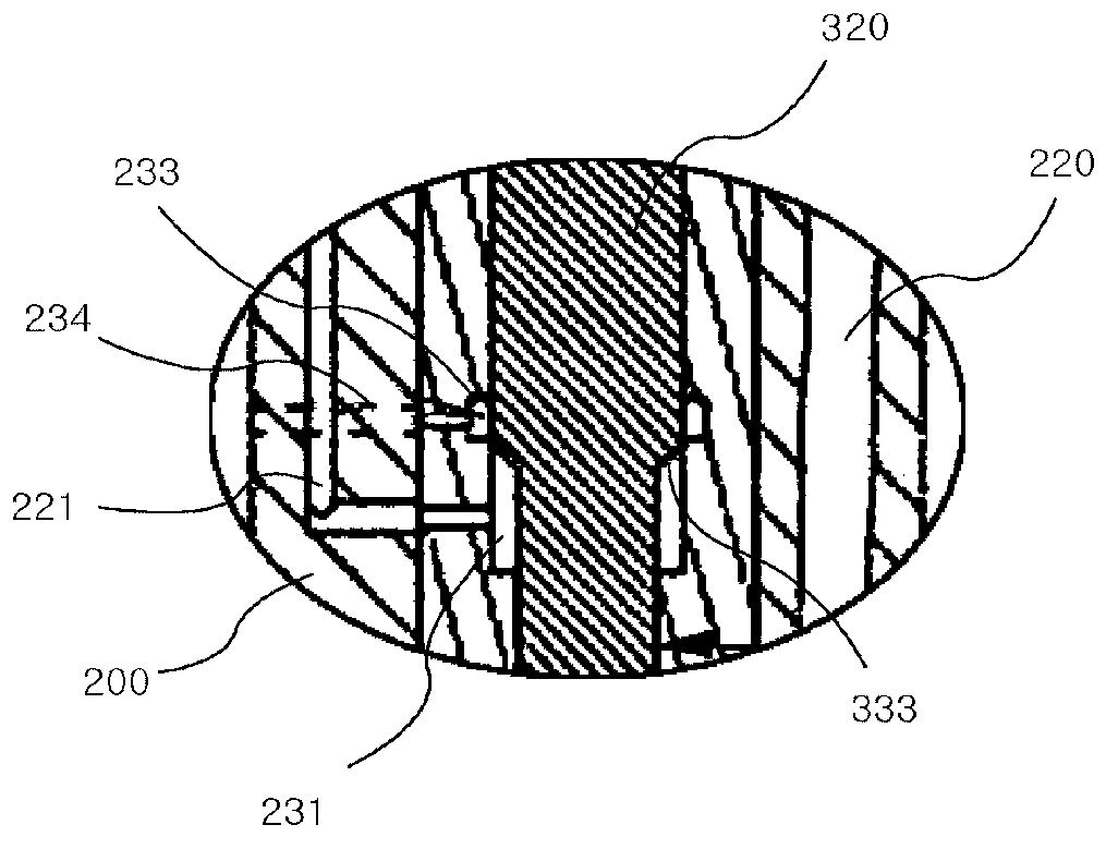
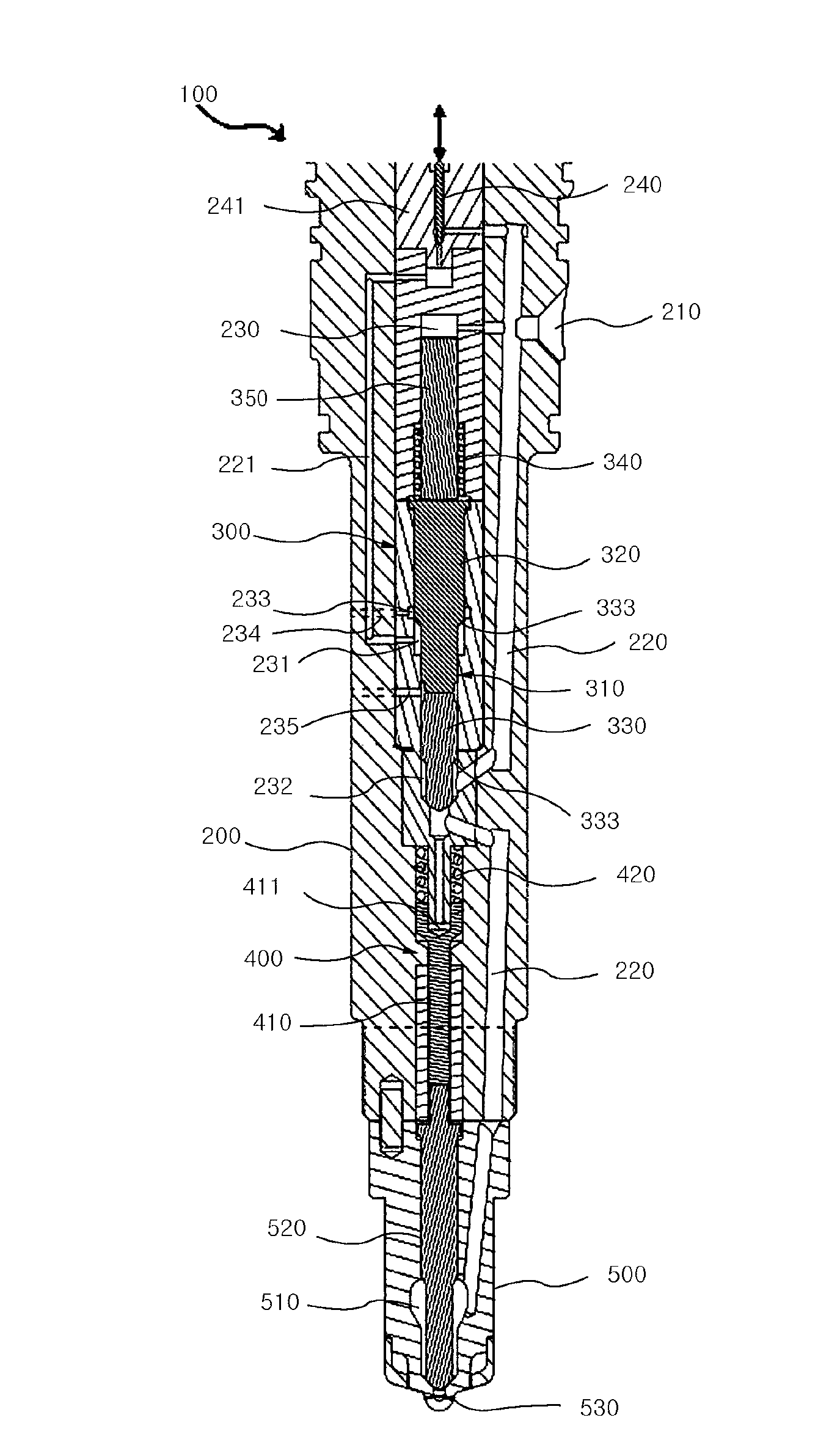
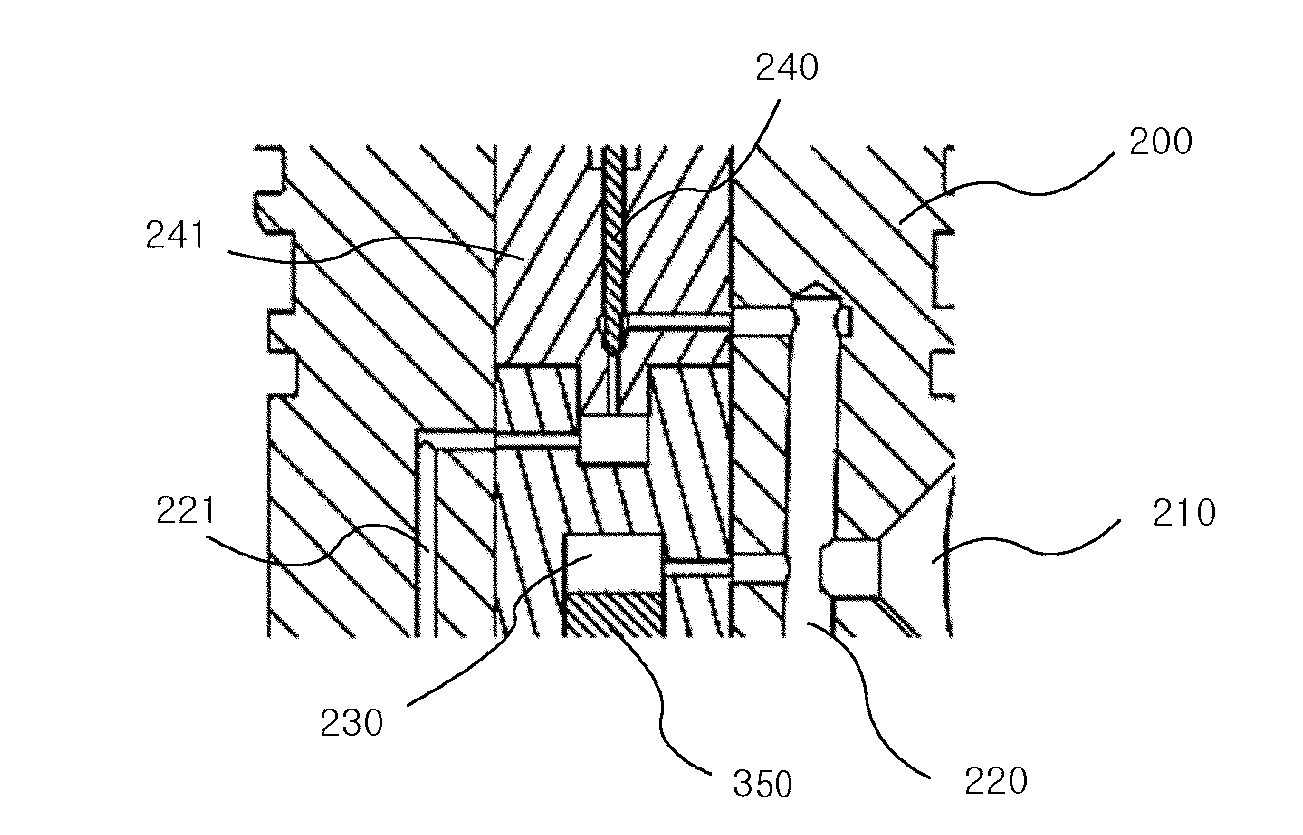
[0049] figure 1 is a schematic diagram showing a fuel injection valve according to a first embodiment of the present invention, figure 2 is a schematic diagram showing in detail the installation structure of the control needle of the fuel injection valve according to the first embodiment of the present invention, image 3 is a schematic view showing in detail the structure of the main shaft and the lower pressure chamber of the fuel injection valve according to the first embodiment of the present invention, Figure 4 It is a schematic diagram showing the fuel outflow hole ...


PUM


Abstract

The present invention relates to an electronically controlled fuel injection valve, and unlike a conventional mechanical fuel injection valve, the electronically controlled fuel injection valve provided by the present invention controls the injection time and the injection amount according to a control signal, independent of driving conditions of an engine, enables swift control of the fuel injection by using as a method for controlling the fuel injection a method that increases the strength of lifting up a cut-off needle of an injection control unit by delivering through a control needle high pressure fuel to a lower pressure chamber, and when the fuel injection is not carried out, fuel is not supplied to a nozzle unit, thereby preventing the high pressure from being applied to the nozzle unit at normal times, and prevents a large amount of fuel from being leaked into a combustion chamber when a component such as the needle is damaged, and processing thereof is easy due to the simple structure of a second fluid channel.

Description

technical field [0001] The present invention relates to an electronically controlled fuel injection valve, and more particularly to an electronically controlled fuel injection valve that enables the timing and amount of fuel injection to be controlled according to a control signal independently of the operating conditions of the engine. High pressure is always applied to the electronically controlled fuel injection valve in the nozzle section. Background technique [0002] With the development of electronic control technology, electronically controlled engines are rapidly spreading. Under this trend, the common rail fuel injection method that can be injected under low load and is easy to control injection according to the control signal is used in electronically controlled engines. mainly applied. [0003] A large amount of research and development has been carried out on the electronically controlled fuel injection valve as the core device of the common rail fuel injection...

Claims


Application Information

Patent Timeline
Patent Type & Authority Applications(China)
IPC IPC(8): F02M61/10F02M61/18F02M61/16F02M51/06
CPCF02M47/046F02M47/06
Inventor 金东勋柳昇协朴泰炯
Owner HYUNDAI HEAVY IND CO LTD
Why Eureka
Try Eureka