Positioning method for inverting blast furnace shell

A blast furnace shell and positioning method technology, which is applied to blast furnaces, blast furnace details, blast furnace parts and other directions, can solve the problems of putting in the furnace frame, unable to lift the furnace belt, limited driving height at the top of the blast furnace, etc., to speed up the construction progress, The effect of reducing construction cost and easy operation

Inactive Publication Date: 2013-10-09
CHINA 19TH METALLURGICAL CORP
View PDF6 Cites 5 Cited by
  • Summary
  • Abstract
  • Description
  • Claims
  • Application Information

AI Technical Summary

Problems solved by technology

[0003] For the reconstruction of the old blast furnace, because the blast furnace is surrounded by the furnace frame, generally in order to save investment, the original old blast furnace frame is used to update the blast furnace, or the blast furnace is expanded. The top distance is small), and the furnace belt cannot be lifted above the hob by driving and moved horizontally, and then put into the hob
Therefore it is not possible to dress
[0004] If it is inverted, first put the nth furnace belt into the furnace frame from the opening on the lower side of the furnace frame, then lift the nth furnace belt and install it on the furnace frame, and then use the same method to lift the mth furnace belt , the method of butt welding with the m+1th belt (m=n-1, n-2, ..., 2, 1, n is a natural number), although theoretically feasible, how to align each belt in the air The positioning is difficult to solve, especially the positioning of multiple furnace belts located in the middle and upper parts of the furnace shell is more difficult

Method used


Image

  • Positioning method for inverting blast furnace shell
  • Positioning method for inverting blast furnace shell
  • Positioning method for inverting blast furnace shell

Examples


Embodiment Construction

[0020] The present invention will be further described below in conjunction with the accompanying drawings and specific embodiments.

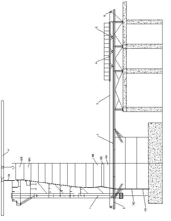
[0021] see figure 1 , remove part of the platform at the tuyere platform on the lower side of the furnace frame 1 as the opening of the furnace shell transportation channel, and install a temporary moving platform on which there are two parallel moving parts extending horizontally into the furnace frame Beams 2, the distance between two moving beams 2 is greater than the maximum diameter of the blast furnace. A track 3 is arranged on the push beam, and the push cart 4 is rolled on the track by the roller 5 at the bottom. The car is connected.

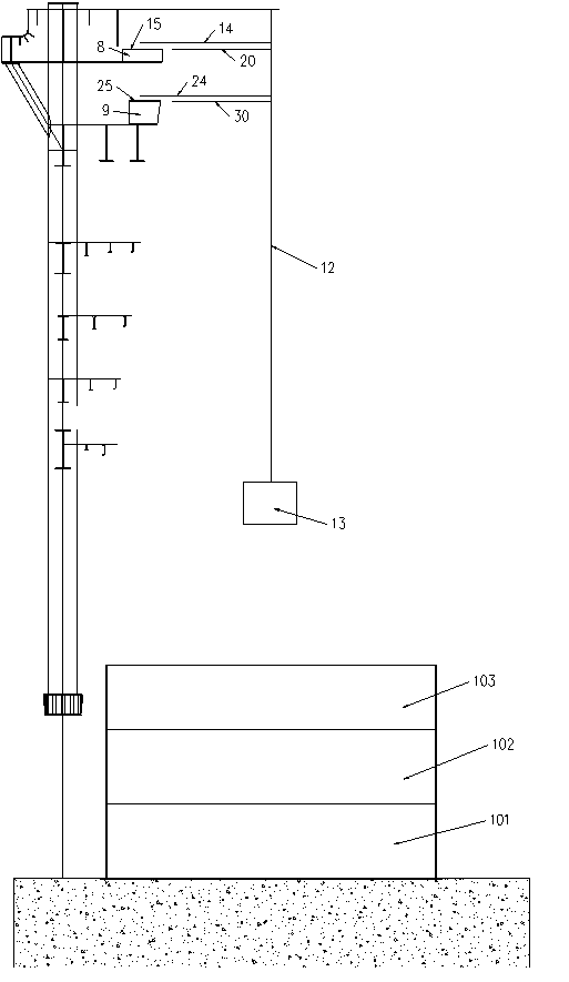
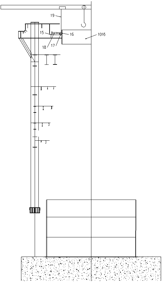
[0022] The furnace shell is composed of 16 furnace belts from bottom to top, which are sequentially composed of the first furnace belt 101, the second furnace belt 102,..., and the sixteenth furnace belt 1016.

[0023] The method of combining the upside down and the upside down of the blast furnace sh...


PUM


Abstract

The invention provides a positioning method for inverting a blast furnace shell. According to the positioning method, furnace zones can be reliably aligned and positioned, the method is simple, the operation is easy and the construction is rapid when the blast furnace shell is inverted. According to the positioning method, the furnace shell sequentially consists of a first furnace zone, a second furnace zone,..., a nth furnace zone from bottom to top. The method comprises the following steps of: during inverting, lifting and mounting the nth furnace zone on a furnace frame, lifting the mth furnace zone, and performing butt welding on the mth furnace zone and the (m+1)th furnace zone, wherein m is equal to (n-1), (n-2),..., 2, 1, and n is a natural number; and during aligning and positioning, finding the center of a blast furnace by a cross line pulling method, pulling a suspension wire, and judging the error between the center of the furnace zone and the center of the blast furnace according to the distance from eight outside markers to an outer ring of the furnace zone and the distance from the other end of a short fine line away from the suspension wire to an inner ring of the furnace zone through circling motion of a long fine line and the short fine line around the suspension wire.

Description

technical field [0001] The invention relates to a positioning method for upside-down blast furnace shells, in particular to a positioning method for furnace belts when the blast furnace shells are upside down. Background technique [0002] The blast furnace shell is sequentially composed of the first furnace zone, the second furnace zone and the nth furnace zone from bottom to top. When installing a blast furnace, the normal installation method is generally adopted, that is, the first furnace belt is installed first, then the second furnace belt is hoisted (lifted), and the second furnace belt and the first furnace belt are butt-welded, so that from bottom to top Install each furnace belt in turn. [0003] For the reconstruction of the old blast furnace, because the blast furnace is surrounded by the furnace frame, generally in order to save investment, the original old blast furnace frame is used to update the blast furnace, or the blast furnace is expanded. The top dista...

Claims


Application Information

Patent Timeline
Patent Type & Authority Applications(China)
IPC IPC(8): C21B7/00
Inventor 王进袁春阳谢德斌申斌贾玲
Owner CHINA 19TH METALLURGICAL CORP
Why Eureka
Try Eureka