System for testing stray current corrosion of buried steel pipeline under function of tensile stress

A technology of stray current and tensile stress, applied in the direction of weather resistance/light resistance/corrosion resistance, measuring devices, instruments, etc., can solve the problems of inability to conduct stray current, small tensile stress, corrosion experiments

Inactive Publication Date: 2015-03-18
BEIJING UNIV OF TECH +1
View PDF3 Cites 0 Cited by
  • Summary
  • Abstract
  • Description
  • Claims
  • Application Information

AI Technical Summary

Problems solved by technology

[0003] In order to overcome the defects of the existing tensile stress test device and tensile stress corrosion test device, such as small tensile stress, low test accuracy, and inability to carry out stray current corrosion experiments, the present invention utilizes screw transmission to generate tensile stress, digital multimeter 19 The value obtained by the high-precision tension sensor 9 is displayed in real time, and the DC power supply 22, the pulse signal generator 21, and the intelligent interrupter 20 are used to generate DC, AC, and AC-DC mixed current stray currents; the constant voltage source 12 is used to generate cathodic protection potential; The workstation 15 performs electrochemical tests on the stressed sample; utilizes the pH meter 14 and the conductivity meter 13 to configure soil solutions with different pH and conductivity and monitors changes in soil solution parameters during the experiment

Method used


Image

  • System for testing stray current corrosion of buried steel pipeline under function of tensile stress
  • System for testing stray current corrosion of buried steel pipeline under function of tensile stress
  • System for testing stray current corrosion of buried steel pipeline under function of tensile stress

Examples


Embodiment Construction

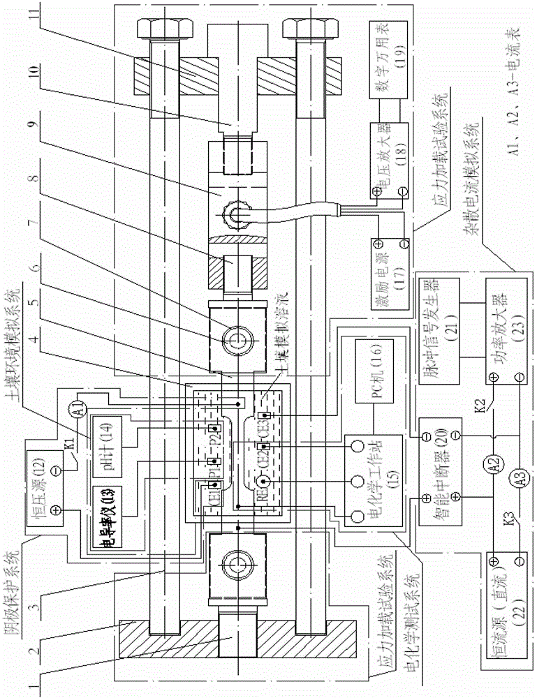
[0023] exist figure 1 In the specific structure of the stray current corrosion test system for buried steel pipelines under the action of tensile stress shown in the present invention, after the stress loading test system is built, use a wrench to simultaneously rotate two long hexagon head bolts 3 through screw transmission. Axial tensile stress is generated, and the pulling force can be changed by adjusting the amount of rotation, and the long hexagon head bolt 3 is stopped rotating until the specified pulling force is observed on the digital multimeter 19 . In the experiment, if it is necessary to adjust the tensile stress of the sample 5, it is only necessary to rotate the long hexagon head bolt 3.

[0024] Build a soil environment simulation system, a stray current simulation system, a cathodic protection system, and an electrochemical test system. Use the soil environment simulation system to configure the required soil solution, and pour the soil solution into the elec...


PUM


Abstract

The invention discloses a system for testing stray current corrosion of a buried steel pipeline under the function of a tensile stress, belonging to the field of corrosion and protection of materials. The system comprises a stress loading experiment system, a soil environment simulating system, a stray current simulating system, a cathodic protection system and an electrochemical testing system. The stress loading experiment system generates a pressure required by a sample experiment; the soil environment simulating system simulates a soil environment in which a buried metal is, and soil solutions with different powers of hydrogen and conductivities are provided; the stray current simulating system generates a direct current, an alternating current and an alternating-current and direct-current mixed stray current; the cathodic protection system provides a cathodic protection potential for the sample; and the electrochemical testing system tests corrosion potentials of the sample under different influence factors. The system is capable of measuring weightlessness, obtaining corrosion morphology, generating the direct current, the alternating current and the alternating-current and direct-current mixed stray current, providing the stress required by the experiment according to the actual running condition, simulating the cathodic protection, and carrying out corrosion rule experiments under different influence factors.

Description

technical field [0001] The invention belongs to the field of material corrosion and protection, and in particular relates to a stray current corrosion test system for buried steel pipelines under the action of tensile stress. Background technique [0002] As my country's buried pipeline network becomes more and more complex, steel pipelines in the pipeline network will cause more and more corrosion problems under the action of factors such as stray current and stress, and the damage will become more and more serious. Therefore, research on buried steel pipelines The law of stray current corrosion is very urgent under stress conditions. Since the stray current is affected by many factors such as soil conductivity and buried depth, and it is difficult to conduct field experiments in the special environment, it is very necessary to establish a stray current corrosion test system for buried steel pipelines under stress conditions. At present, there is a single tensile stress tes...

Claims


Application Information

Patent Timeline
Patent Type & Authority Patents(China)
IPC IPC(8): G01N17/02
Inventor 王力伟唐兴华王新华何仁洋王翠
Owner BEIJING UNIV OF TECH
Why Eureka
Try Eureka