Imaging device and its power supply control method, power wake-up device and control system

A technology for imaging devices and wake-up devices, which is applied in the direction of program control, electrical program control, and circuit devices in sequence/logic controllers, which can solve problems such as inconvenient use for users and non-working control units of imaging devices, and achieve power saving Effect

Active Publication Date: 2016-05-25
ZHUHAI PANTUM ELECTRONICS
View PDF6 Cites 0 Cited by
  • Summary
  • Abstract
  • Description
  • Claims
  • Application Information

AI Technical Summary

Problems solved by technology

However, after the mains power supply of the imaging device is cut off, the control unit of the imaging device does not work, and how to start the imaging device again becomes a difficult problem
If the user is far away from the imaging device, the user needs to walk to the side of the imaging device to start it, causing inconvenience to the user

Method used


Image

  • Imaging device and its power supply control method, power wake-up device and control system
  • Imaging device and its power supply control method, power wake-up device and control system
  • Imaging device and its power supply control method, power wake-up device and control system

Examples


Embodiment 1

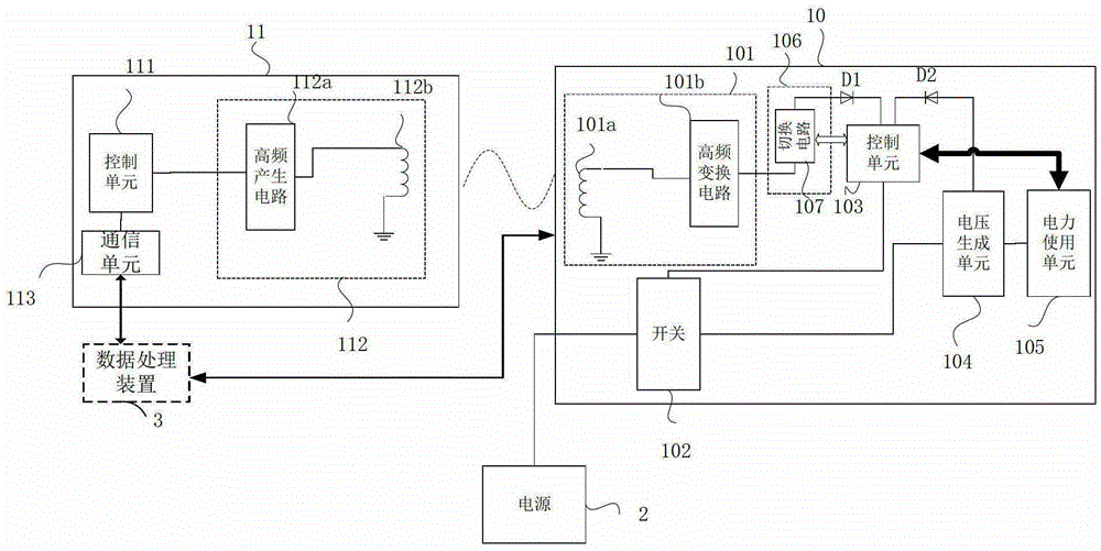
[0049] figure 1 It is a structural block diagram of a power control system for an imaging device according to an embodiment of the present invention. The power control system includes the imaging device 10 and the power wake-up device 11 that transmits wireless power to a radio receiving unit 101 (details will be described later) of the imaging device 10 . The power wake-up device 11 controls the power supply of the imaging device 10 and can also provide power to the control unit 103 of the imaging device 10 . The solid lines with double arrows in the drawings of the present invention represent wired data or wireless data connections.

[0050] The power wake-up device 11 is located outside the imaging device 10 and includes a control unit 111 , a radio transmission unit 112 , and a communication unit 113 . An external power supply (not shown in the figure) supplies power to the control unit 111 and the radio transmitting unit 112. The power supply may be any power supply tha...

Embodiment 2

[0076] This embodiment focuses on the parts that are different from the first embodiment, and will not repeat the description of the parts that are roughly the same as the first embodiment. As long as there is no conflict, the description in the first embodiment is also applicable to the second embodiment. Steps, units or circuits in this embodiment that are substantially the same as those in Embodiment 1 use the same reference numerals.

[0077] Figure 4 It is a structural block diagram of the power control system of this embodiment. From Figure 4It can be seen that, unlike the previous embodiment, no power switching unit is provided between the high-frequency conversion circuit 401b of the imaging device 40 and the control unit 403 in this system.

[0078] Figure 5 A flowchart showing power supply to the imaging device 40 by the power supply control system according to the present embodiment. Since the power switching unit between the high-frequency conversion circui...


PUM


Abstract

The invention discloses an imaging device and a power supply control method thereof, a power supply awaking device and a control system. The imaging device comprises a control unit and a power using unit, and the imaging device further comprises a first power supply portion and a second power supply portion, wherein the first power supply portion is used for at least providing power for the power using unit using an external wired power supply, and when the imaging device judges that a first preset power-off condition is met, the external wired power supply is cut off to cut off power supplied for the power using unit; the second power supply portion comprises a radio receiving unit used for receiving radio power and providing the received radio power to the control unit. By means of the imaging device, power is saved, safety and stability are guaranteed, and the imaging device can be restarted conveniently.

Description

technical field [0001] The invention relates to the field including digital imaging, and the invention relates to an imaging device and a power supply control method thereof, a power wake-up device and a control system. Background technique [0002] Imaging devices, scanning devices, and the like have been widely used. In order to meet the demand for energy saving, an imaging device is proposed in the prior art. If there is no imaging operation on the imaging device for a period of time, the imaging device enters an energy saving mode. In the energy-saving mode, the functional execution units with large power consumption such as the fixing unit and the motor drive unit of the imaging device are cut off, and only power is supplied to the control unit, so as to achieve the effect of energy saving. When an imaging operation is required, the control unit controls to resume supply of power to the function performing unit. [0003] However, in real life, there are often situatio...

Claims


Application Information

Patent Timeline
Patent Type & Authority Patents(China)
IPC IPC(8): G05B19/04H02J50/00H02J50/12
Inventor 尹爱国
Owner ZHUHAI PANTUM ELECTRONICS
Why Eureka
Try Eureka