Wire connector

A wire connector and main connection technology, which is applied in the direction of connections, current collectors, contact parts, etc., can solve problems such as poor connection stability and potential safety hazards of metal conductive strips, and achieve improved stability, convenience and safety, and easy operation Effect

Inactive Publication Date: 2013-10-09
万能亿工业科技发展(苏州)有限公司
View PDF6 Cites 5 Cited by
  • Summary
  • Abstract
  • Description
  • Claims
  • Application Information

AI Technical Summary

Problems solved by technology

[0002] The connector in the traditional distribution box is generally a metal conductive strip, on which there are several threaded holes, and the wires are connected to each other through screws. Although the structure of this connector is simple, the connection stability is poor, and the exposed metal conducts electricity. There are also security risks

Method used


Image

  • Wire connector
  • Wire connector
  • Wire connector

Examples


Embodiment Construction

[0030] Further description will be made below in conjunction with the accompanying drawings,

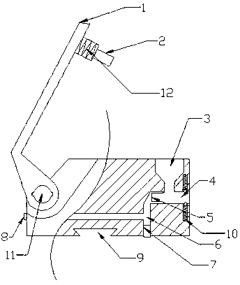
[0031] Such as figure 1 As shown, the present invention includes a rotating arm 1, a pressing block 2, a pressing opening 3, a wire groove 4, a wire contact 5, a conductive metal sheet 6, a hollow rotating shaft 11, a main connecting contact 7 and a secondary connecting contact 8, The base of the connector is a rectangular parallelepiped. On one of the edges of the rectangular parallelepiped, there is a rotating arm 1 that can elastically rotate around the base. On the rotating arm 1, a pressing block 2 is arranged. 12 Elastic connection, a press-in opening 3 is processed on the base, by turning the rotating arm 1, the pressing block 2 on the rotating arm 1 is pressed into the pressing-in opening 3 on the base, inside the base, the pressing block 2 is pressed into the opening The bottom of the hole 3 is also provided with a wire groove 4 perpendicular to the axis of the press-in hol...


PUM


Abstract

The invention discloses a wire connector. A conducting structure and a wire patchhole are arranged in a plastic base, and a wire is tightly pressed through a rotating arm. Compared with a traditional wire connector, the wire connector has the advantages that safety is higher, operation is much simpler, meanwhile the number and path of wiring can be combined at will through a specially-made rail, the wire connector is suitable for various working conditions, and good social benefits are provided.

Description

technical field [0001] The invention relates to a connector, which belongs to the field of electric appliances. Background technique [0002] The connector in the traditional distribution box is generally a metal conductive strip, on which there are several threaded holes, and the wires are connected to each other through screws. Although the structure of this connector is simple, the connection stability is poor, and the exposed metal conducts electricity. There are also security risks. Contents of the invention [0003] The present invention adopts a technical solution capable of solving the above technical problems. [0004] The present invention is realized by following method: [0005] A connector, the connector includes a base, a pressing block, a rotating arm, a main connection contact, a conductive metal sheet, and a wire contact, the base is a cuboid structure, the pressing block is arranged on the rotating arm, The base is also provided with a press-in opening...

Claims


Application Information

Patent Timeline
Patent Type & Authority Applications(China)
IPC IPC(8): H01R4/52H01R41/00H01R11/12H01R13/02H01R13/639
Inventor 李春林
Owner 万能亿工业科技发展(苏州)有限公司
Why Eureka
Try Eureka