
Load cell and method for adjusting a load cell

A weighing sensor and weighing system technology, applied in the field of weighing sensors, can solve problems such as the possibility of designing unfavorable load joints

Active Publication Date: 2013-10-09
SARTORIUS LAB INSTR GMBH & CO KG
View PDF8 Cites 5 Cited by
  • Summary
  • Abstract
  • Description
  • Claims
  • Application Information

AI Technical Summary

Problems solved by technology

However, this disadvantageously limits the design possibilities in the vicinity of load junctions (e.g. balance pans on load boom arms)

Method used


Image

  • Load cell and method for adjusting a load cell
  • Load cell and method for adjusting a load cell
  • Load cell and method for adjusting a load cell

Examples


Embodiment Construction

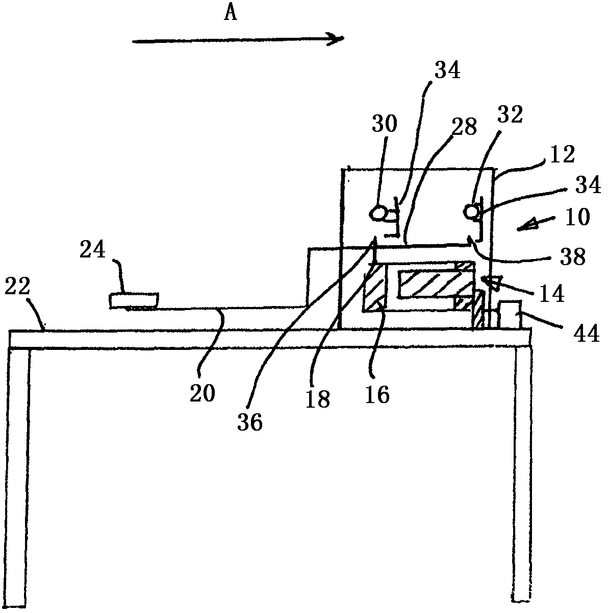
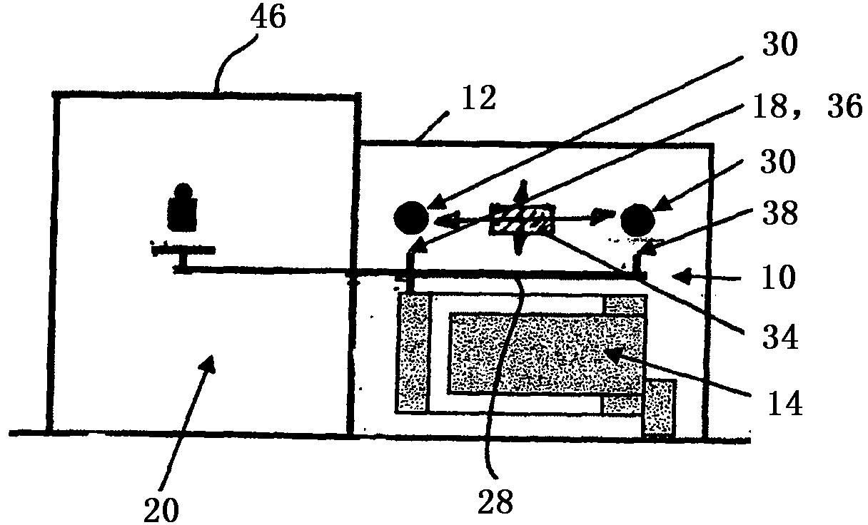
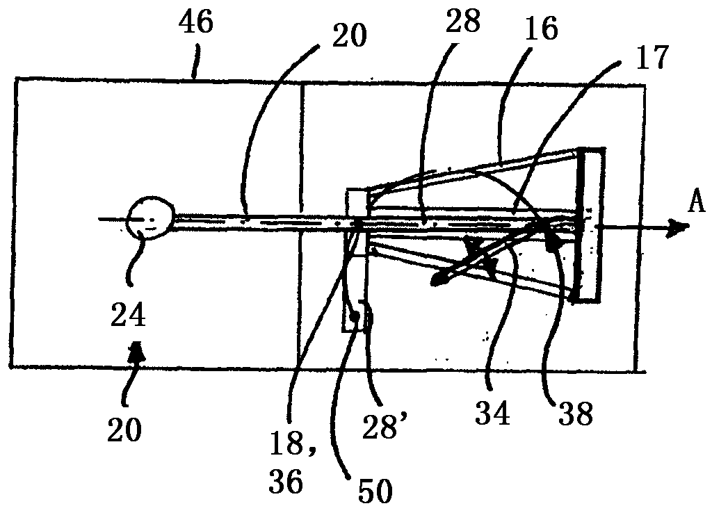
[0032] figure 1 A load cell 10 is shown with a housing 12 . Inside the housing 12 is a weighing system 14, which preferably includes a parallelogram 16 that transmits the applied load to a weighing boom 17 (see image 3 ).

[0033]At one end of the parallelogram 16 there is a point of application 18 at which a load boom arm 20 protruding from the housing is incorporated into the weighing system.

[0034] The load boom arm 20 preferably extends horizontally within the housing 12 and is angled downwardly outside the housing 12 such that said downwardly angled portion extends adjacent to and along the table top 22 .

[0035] The distance between the downwardly angled portion of the load boom arm 20 and the table top 22 is minimal.

[0036] Attached to one end of the load boom arm 20 is a plate 24 capable of containing the item to be weighed.

[0037] The load boom arm 20 is releasably secured by, for example, a connector (not shown).

[0038] As a top view ( image 3 ), the...


PUM


Abstract

The invention relates to a load cell (10) with a weighing system (14) having a force application point (18), a load cantilever (20) for receiving the loads to be weighed at a position remote from the force application point (18) and an adjustment device, wherein an adjustment weight cantilever (28) is provided, which extends in a longitudinal direction (A) defined by the load cantilever, on the side opposite the load cantilever (20) relative to the force application point (18) and which comprises at least two adjustment weight engagement points (36, 38) that are preset on said adjustment weight cantilever. According to the invention, an activation unit (34) places at least one adjustment weight (30, 32) on the adjustment weight engagement points (36, 38).

Description

technical field [0001] The invention relates to a load cell having: a weighing system having a point of application of force; a load boom arm for receiving a load to be weighed at a location remote from the point of application of force; and Adjustment device, wherein, in top view, the load boom arm extends in the longitudinal direction from the force application point to the load cell. Background technique [0002] The load cell is actually the heart of the electromechanical balance. Typically, a parallelogram, also called a transmission rod, is accommodated in the load cell, the parallelogram having to transmit the load to the weighing boom. The force acting on the weighing boom is measured by using the well-known electromagnetic force compensation method. In a load cell, the force is directed to a predetermined point of application. When the load boom arm is used, the load to be weighed is not located above the outside of the point of application of the load cell, but ...

Claims


Application Information

Patent Timeline
Patent Type & Authority Applications(China)
IPC IPC(8): G01G23/01
CPCG01G23/01G01G23/012
Inventor 米夏埃尔·劳布施泰因
Owner SARTORIUS LAB INSTR GMBH & CO KG
Learn More