Eureka AIR delivers breakthrough ideas for toughest innovation challenges, trusted by R&D personnel around the world.

Foundry sand box locking device

A technology of locking device and sand box, which is applied to casting molding equipment, mold boxes, manufacturing tools, etc., can solve the problems of cumbersome locking process, time-consuming and labor-intensive, etc., and achieve the effect of improving the efficiency of casting work.

Inactive Publication Date: 2013-10-16
诸城市华欣铸造有限公司
View PDF0 Cites 9 Cited by
  • Summary
  • Abstract
  • Description
  • Claims
  • Application Information

AI Technical Summary

Problems solved by technology

[0002] In foundry production, the upper box and the lower box of the casting mold sand box were locked by clamping method before, and two people were required to operate at the same time, the locking process was cumbersome, time-consuming and labor-intensive

Method used


Image

  • Foundry sand box locking device
  • Foundry sand box locking device

Examples


Embodiment Construction

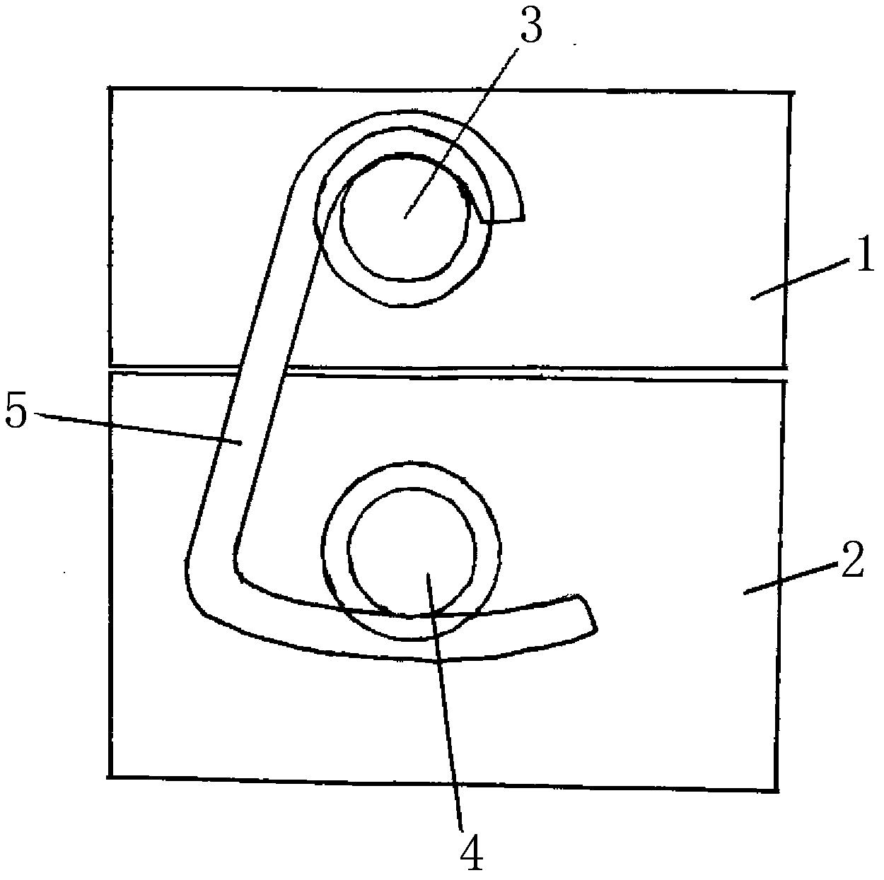
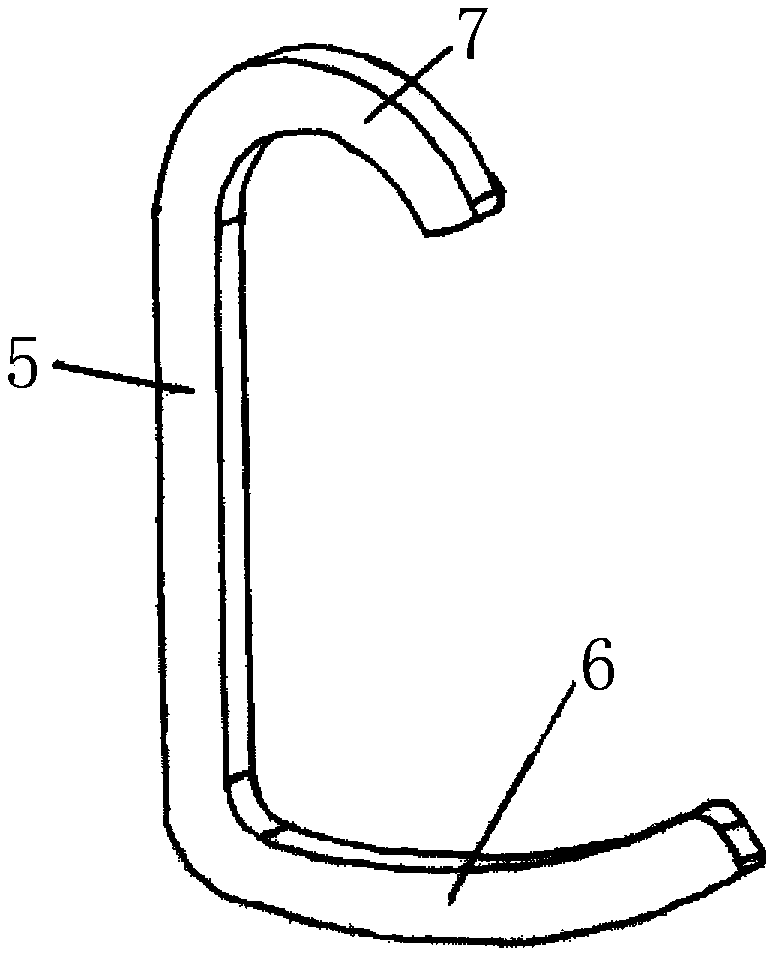
[0010] like figure 1 , 2 As shown, the present invention is respectively provided with upper box claw 3 and lower box claw 4 at the middle part of one side of upper sand box 1 and lower sand box 2, and a hook 5 is hung between the upper box claw 3 and the lower box claw 4, The two ends of described hook 5 are respectively provided with arc-shaped large hook 6 and small hook 7, and large hook 6 and small hook 7 are respectively hung on upper case claw 3 and lower case claw 4, and upper sand box 1 and The lower sand box 2 is locked together.

[0011] Through the above arrangement, the locking of the upper sand box 1 and the lower sand box 2 of the present invention saves labor and time, and the locking is firm, and it is not easy to loosen between the upper sand box 1 and the lower sand box 2 when pouring products.


PUM


Abstract

The invention discloses a foundry sand box locking device which is characterized in that an upper box claw and a lower box claw are respectively arranged at the middle parts on one side of an upper sand box and one side of a lower sand box, a hook is hung between the upper box claw and the lower box claw, a big circular arc-shaped hook and a small circular arc-shaped hook are respectively arranged at two ends of the hook, and are respectively hung on the upper box claw and the lower box claw, and the upper box claw and the lower box claw are locked together. Through the arrangement, the invention provides the sand box locking tool, which locks and fixes the upper box claw and the lower box claw quickly in a labor-saving manner and improves the casting working efficiency.

Description

technical field [0001] The invention relates to a locking device, in particular to a locking device used on a casting sand box. Background technique [0002] In foundry production, the upper box and the lower box of the casting mold sand box were locked by clamping method in the past, and two people were required to operate at the same time, and the locking process was cumbersome, time-consuming and labor-intensive. Contents of the invention [0003] The object of the present invention is to provide a casting flask locking device with simple structure and convenient locking. [0004] In order to achieve the above object, the present invention is respectively provided with an upper box claw and a lower box claw at the middle of one side of the upper sand box and the lower sand box, and a hook is hung between the upper box claw and the lower box claw. The two ends are respectively provided with arc-shaped large hooks and small hooks, and the large hooks and small hooks are ...

Claims


Application Information

Patent Timeline
IPC IPC(8): B22C21/08
Inventor 魏本欣魏玉明隋鹏举
Owner 诸城市华欣铸造有限公司
Why Eureka
Eureka Blog
Learn More