Cable identification ring

A technology for identification rings and cables, applied in the field of identification rings, can solve problems such as optical fiber extrusion, optical cable sheath stress deformation, and poor transmission performance, and achieve the effects of avoiding direct friction, not easy to wear, and clear writing

Inactive Publication Date: 2013-10-16
卓开富
View PDF10 Cites 2 Cited by
  • Summary
  • Abstract
  • Description
  • Claims
  • Application Information

AI Technical Summary

Problems solved by technology

When the number rings described in these two patents are used tightly on the optical cable, it will cause the cable sheath to be deformed by force, which will cause the optical fiber in the optical cable to be squeezed, and the transmission performance will deteriorate. In severe cases, the optical fiber will be damaged. Breaks and will wear out the characters of the logo during the movement

Method used


Image

  • Cable identification ring
  • Cable identification ring
  • Cable identification ring

Examples


Embodiment Construction

[0018] The technical solutions of the present invention will be clearly and completely described below in conjunction with the accompanying drawings of the present invention. Obviously, the described embodiment is only one embodiment of the present invention, not all embodiments. Based on the embodiments of the present invention, all other embodiments obtained by persons of ordinary skill in the art without creative efforts fall within the protection scope of the present invention.

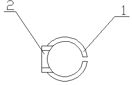
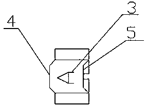
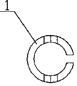
[0019] figure 1 and figure 2 It is an embodiment of the present invention. A cable identification ring, the section of which is "C" shaped, and an identification area is set on the identification ring, and the identification area is a cuboid protruding from the outer surface of the identification ring. There are concave characters on the identification area, and the concave fonts or symbols are filled with black ink, and the writing of the concave characters is clearer and not easy to wear. Th...


PUM


Abstract

The invention provides a cable identification ring which has a C-shaped section. An identification area is formed in the identification ring; a character filled with printing ink is arranged on the identification area; the character is a concave character or a convex character; the identification area is one or more of the outer surface of the identification ring, a protruding platform on the outer surface of the identification ring, and a downwards concave platform on the outer surface of the identification ring; a bulge is formed on the edge of the identification ring; a lower recess is formed in the other side which corresponds to the bulge. The C-shaped section is directly matched with the shape of a cable, so that the cable is prevented from being extruded through the identification ring; due to matching between the edge bulge and the small recess among lantern rings, the problem that the identifier rotates and moves is solved, the identification character is clear due to the concave or convex character, and the identification ring is difficult to wear.

Description

technical field [0001] The invention relates to an identification ring, in particular to a cable identification ring which is assembled on a line cable and marked with clear and wear-resistant characters. Background technique [0002] At present, the common practice in the industry is to use a short cylindrical hollow identification ring made of plastic, and put it on a small-sized tight-sleeved optical cable during wiring. However, this solution will cause the number ring to slide and rotate on the optical cable, and a code display will appear. Confusion and other situations bring certain difficulties to assembly and post-maintenance. [0003] Solutions are provided in published patents such as: the patent application number CN 201707839 U describes a number ring with an improved structure, which is an inverted U-shaped clamp block, on both sides of the open end of the clamp block, facing The inner wall of the closed end is formed with two non-slip sharp strips distributed...

Claims


Application Information

Patent Timeline
Patent Type & Authority Applications(China)
IPC IPC(8): G09F7/00
Inventor 卓开富
Owner 卓开富
Why Eureka
Try Eureka