

Magnetic resonance imaging apparatus and method
A magnetic resonance imaging and image technology, which is applied in measuring devices, image enhancement, image analysis, etc., can solve the problems of not elucidating cerebrospinal fluid, not establishing magnetic resonance imaging, etc.
- Summary
- Abstract
- Description
- Claims
- Application Information
AI Technical Summary
Problems solved by technology
Method used
Image

Examples
no. 1 Embodiment approach )
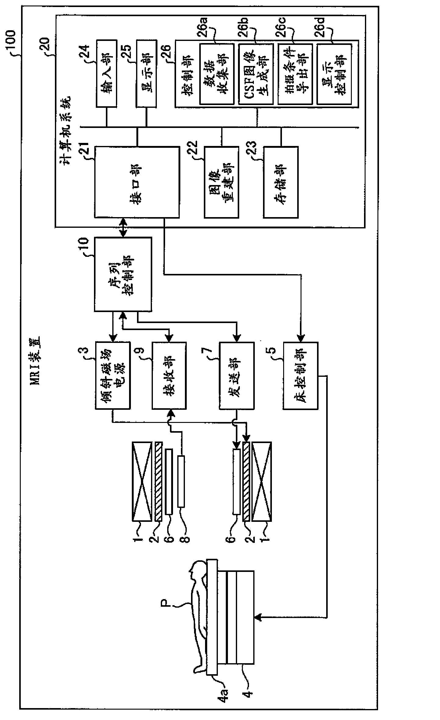
[0034] Embodiments of a magnetic resonance imaging apparatus (hereinafter, appropriately referred to as “MRI apparatus”) and methods will be described below. figure 1 It is a block diagram showing the configuration of the MRI apparatus 100 according to the first embodiment. In addition, the subject P is not included in the MRI apparatus 100 .
[0035] The static field magnet 1 is formed in a hollow cylindrical shape, and generates a uniform static magnetic field in the inner space. The static field magnet 1 is, for example, a permanent magnet, a superconducting magnet, or the like. The gradient magnetic field coil (coil) 2 is formed in a hollow cylindrical shape, and generates a gradient magnetic field in the inner space. Specifically, the gradient coil 2 is disposed inside the static field magnet 1 , receives a current supply from the gradient power supply 3 , and generates a gradient magnetic field. The gradient magnetic field power supply 3 supplies current to the gradie...
no. 2 Embodiment approach )
[0078] Next, a second embodiment will be described. In the second embodiment, an example in which k-space data is simply divided into two segments in the phase encoding direction has been described, but the embodiment is not limited to this. In addition, the MRI apparatus 100 according to the second embodiment may have the same configuration as that of the MRI apparatus 100 according to the first embodiment, except for the cases particularly mentioned.
[0079] Figure 11 It is a diagram for explaining the relationship between data collection and segments in the second embodiment. Such as Figure 11 As shown, for example, the data collection unit 26a collects the data of the low-frequency region of k-space covering multiple time phases within one respiratory cycle, and also collects the data of the high-frequency region of k-space covering multiple time phases within one respiratory cycle data. At this time, the CSF image generation unit 26b combines the data of the low-fr...
no. 3 Embodiment approach )
[0095] Next, a third embodiment will be described. In the above embodiments, it has been described that the start of inhalation or the start of exhalation is used as a trigger, and an inversion pulse is applied to selectively collect a desired period in the respiratory cycle (for example, a period with large respiratory fluctuations, Exhalation period, inhalation period) data example. However, embodiment is not limited to this. In addition, the MRI apparatus 100 according to the third embodiment may have the same configuration as the MRI apparatus 100 according to the other embodiments, except for the cases particularly mentioned.
[0096] In the third embodiment, the data collection unit 26 a continuously collects data of the imaging region independently of the respiratory cycle of the subject P. In addition, the data collection unit 26a simultaneously collects data showing the phase of the respiratory cycle. Then, the CSF image generation unit 26b selectively generates CS...
PUM
 Abstract
Description
Claims
Application Information