Eureka AIR delivers breakthrough ideas for toughest innovation challenges, trusted by R&D personnel around the world.

a ditching machine

A technology of ditching machine and ditching knife, which is applied in the direction of earth mover/shovel, construction, etc. It can solve the problems of unadjustable ditch width and shape, low ditching efficiency, high failure rate, etc., and achieve continuous ditching Strong performance, high ditching efficiency and low energy consumption

Inactive Publication Date: 2016-02-24
北京阳光五洲科技发展有限公司
View PDF5 Cites 0 Cited by
  • Summary
  • Abstract
  • Description
  • Claims
  • Application Information

AI Technical Summary

Problems solved by technology

[0006] The present invention proposes a ditching machine, which is used to solve the problems of the existing ditching equipment, such as the existing ditching equipment with structural defects, which make the width and shape of the ditching impossible to adjust, high energy consumption, high failure rate and low ditching efficiency

Method used


Image

  • a ditching machine
  • a ditching machine
  • a ditching machine

Examples


Embodiment Construction

[0073] The following will clearly and completely describe the technical solutions in the embodiments of the present invention with reference to the accompanying drawings in the embodiments of the present invention. Obviously, the described embodiments are only some, not all, embodiments of the present invention. Based on the embodiments of the present invention, all other embodiments obtained by persons of ordinary skill in the art without creative efforts fall within the protection scope of the present invention.

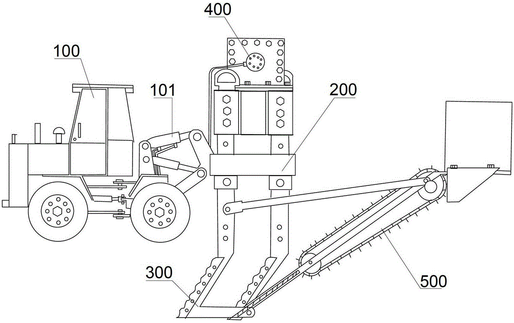
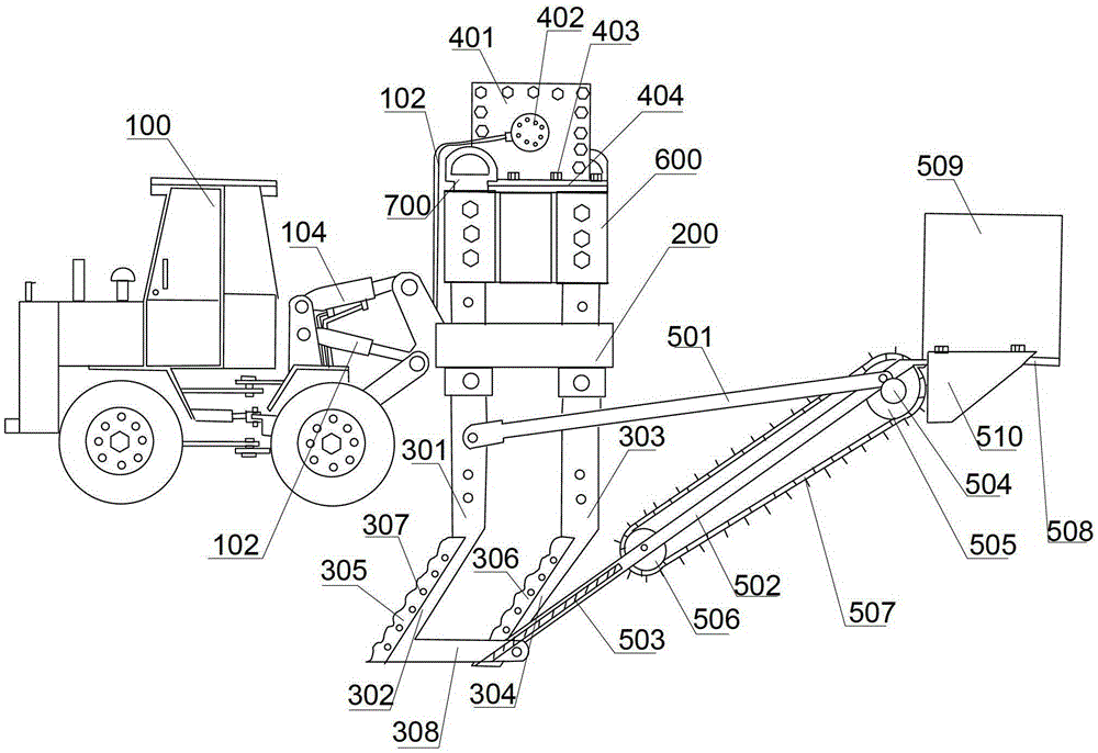
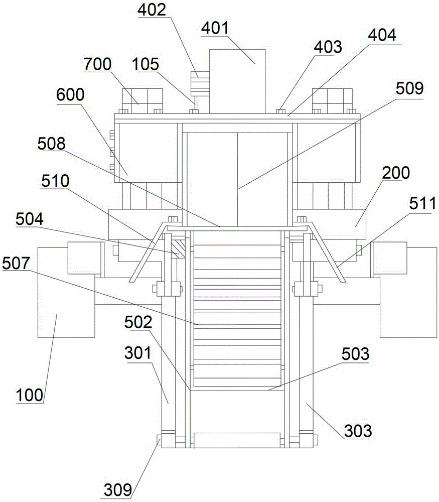
[0074] Such as figure 1 As shown, one embodiment of the present invention provides a kind of ditching machine, comprising:

[0075] The power host 100; the power host 100 includes: an operation control system; a suspension mechanism 101, which is arranged at the rear end of the power host 100;

[0076] The frame 200 is connected with the suspension mechanism 101;

[0077] The ditching device 300 is arranged below the frame 200 and connected with the frame 200;

...


PUM


Abstract

The invention provides a ditching machine used for solving the problems, in the conventional ditching equipment, that the width and shape of ditching is nonadjustable, the energy consumption and failure rate are high, and the ditching efficiency is low due to structure defects. The ditching machine comprises a power main engine, wherein the power main engine comprises an operation control system, a suspension mechanism, a rack, a ditching device, a vibration device and a soil treatment mechanism; the suspension mechanism is arranged at the back end of the power main engine and connected with the operation control system; the rack is connected with the suspension mechanism; the ditching device is arranged below the rack and connected with the rack; the vibration device used for making the ditching device to perform cutting reciprocating vibration from front to back horizontally is arranged on the rack and connected with the operation control system and the rack; the soil treatment mechanism used for turning up soil ditched by the ditching machine under the drive of the vibration device and transporting the soil to two sides of ditching is arranged behind the ditching device and connected with the ditching device. The ditching machine has the advantages that ditches with different shapes, width and depth can be ditched, the failure rate is low, the energy consumption is low, and the work efficiency is high.

Description

technical field [0001] The invention relates to the technical field of ditching equipment, in particular to a ditching machine. Background technique [0002] At present, there are various types of equipment for ditching on the market, such as bucket type, coulter type, wheel type, chain type and the like. These types of trenching equipment suffer from the following disadvantages: [0003] 1. Digging bucket type ditching equipment, the ditch width cannot be adjusted or the adjustable range is small, the shape of the ditch cannot be adjusted, and the work is single excavation, discontinuous, and low work efficiency; [0004] 2. Coulter type, wheel type, and chain type ditching equipment can work continuously during ditching operations, but the work efficiency is low, the shape and width of the ditching cannot be adjusted, and the energy consumption is large and the failure rate is high . [0005] It can be seen that the existing ditching equipment has structural defects, so...

Claims


Application Information

Patent Timeline
Patent Type & Authority Patents(China)
IPC IPC(8): E02F5/02E02F5/14E02F5/30E02F7/02
Inventor 周立伟
Owner 北京阳光五洲科技发展有限公司
Why Eureka
Eureka Blog
Learn More