Ditching auxiliary device of novel ditcher

An auxiliary device and ditching machine technology, applied in the direction of circuit devices, battery circuit devices, transportation and packaging, etc., can solve the problems of blade wear, low efficiency, and large labor time, so as to reduce wear and prolong service life Effect

Active Publication Date: 2021-05-07
浙江高博卫浴有限公司
View PDF8 Cites 0 Cited by
  • Summary
  • Abstract
  • Description
  • Claims
  • Application Information

AI Technical Summary

Problems solved by technology

[0002] The ditching machine is a new efficient and practical ditching device. After the diesel engine transmits the rotation to the clutch through the belt, it drives the traveling gearbox, transmission shaft, and rear axle. Wait to realize the forward or backward linear motion of the chain type ditching machine for ditching machinery. With the development of the economy, the country has increased its efforts in capital construction, and the number of underground pipelines and electric (optical) cable laying projects has increased sharply. The quality requirements are improved, and the manual excavation method is not only inefficient, but the poor quality of the trench will not meet the needs of construction
[0003] At present, during the use of the trencher, especially when trenching in places with high soil moisture or high soil viscosity after rainy days, the mud retaining of the trencher Mud is easy to accumulate on the board and the ditching knife, which will hinder the operation of the ditching knife, and it needs to be cleaned up in time, which takes a lot of manpower time and reduces the ditching efficiency. The driver needs to reduce the speed in time to reduce the damage to the blade. The current trencher driver cannot know the internal situation of the soil at the first time, which leads to serious wear of the blade. For this reason, we propose a new type of ditching machine Ditching Aids for Machines

Method used


Image

  • Ditching auxiliary device of novel ditcher
  • Ditching auxiliary device of novel ditcher
  • Ditching auxiliary device of novel ditcher

Examples


Embodiment

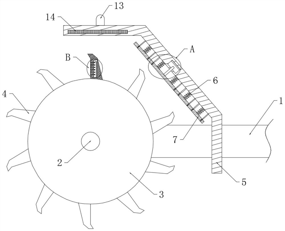
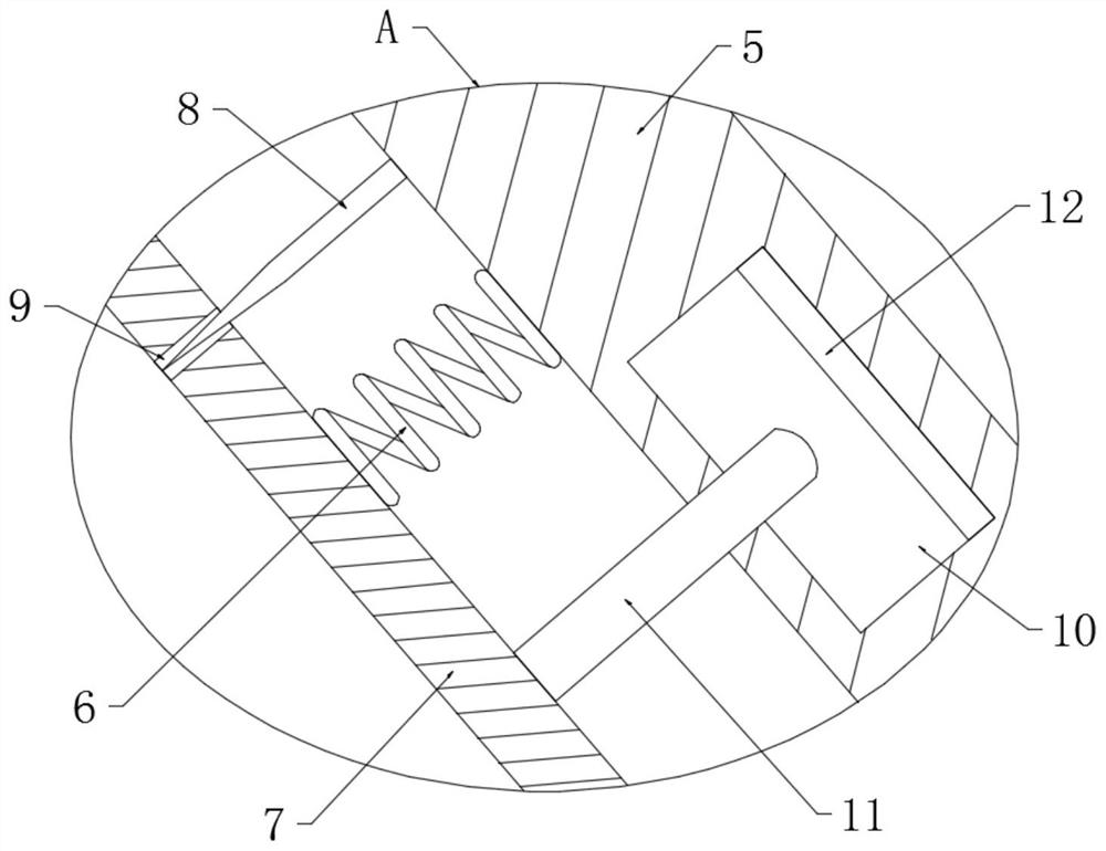
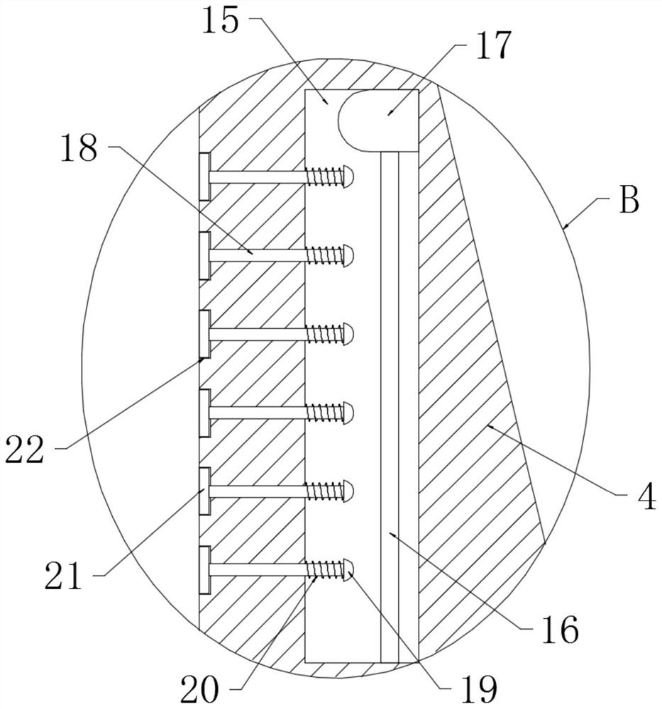
[0022] refer to Figure 1-4 , a new type of ditching auxiliary device for ditching machine, including a connecting frame 1 and a drive shaft 2 arranged on the connecting frame 1, a ditching wheel 3 is fixedly connected above the driving shaft 2, and the annular surface of the ditching wheel 3 is uniform A plurality of shovel blades 4 are welded, a protective plate 5 is welded on the connecting frame 1, and a plurality of shock-absorbing springs 6 are fixedly connected to the inclined plate surface of the side of the protective plate 5 close to the ditching wheel 3, and a plurality of shock-absorbing springs 6 One end away from the protection plate 5 is commonly connected with a fender 7, the side wall of the protection plate 5 close to the fender 7 is vertically fixed with a plurality of plastic needles 8, and the fender 7 is provided with a plurality of needle holes 9 , each pinhole 9 is slidably connected with a plastic needle 8, and a thin layer of silk cloth is adhered to ...


PUM


Abstract

The invention discloses a ditching auxiliary device of a novel ditcher. The ditching auxiliary device comprises a connecting frame and a driving shaft arranged on the connecting frame, and is characterized in that a ditching wheel is fixedly connected above the driving shaft, a plurality of scraper knives are uniformly welded on the annular surface of the ditching wheel, a protective plate is welded on the connecting frame, a plurality of damping springs are fixedly connected to an inclined plate face of the side, close to the ditching wheel, of the protective plate, and the ends, away from the protective plate, of the damping springs are jointly connected with a fender. The ditching auxiliary device disclosed by the invention has the advantages that when a cutting machine is used for ditching on ground with a large amount of pebbles, the fender is continuously impacted, a piezoelectric ceramic plate continuously charges a recoverable capacitor to break down the recoverable capacitor, at the moment, one lead of the recoverable capacitor can be recovered, the current passes through a prompting lamp to enable the prompting lamp to emit light to enable a person driving the cutting machine to see and adjust the rotating speed of a cutting wheel in time, the abrasion of the pebbles to the scraper knives is reduced, and the service life of the scraper knives is prolonged.

Description

technical field [0001] The invention relates to the technical field of trenching machine equipment, in particular to a trenching auxiliary device of a novel trenching machine. Background technique [0002] The ditching machine is a new type of efficient and practical ditching device. After the diesel engine transmits the rotation to the clutch through the belt, it drives the traveling gearbox, transmission shaft, rear axle, etc. to realize the forward or backward movement of the chain ditching machine. With the development of the economy, the state has intensified efforts on capital construction, the number of underground pipelines and electrical (optical) cable laying projects has surged, and the quality requirements have improved. The manual excavation method is not only inefficient, but also ditching. Poor quality troughs will not be able to meet the needs of the construction. [0003] At present, when the trencher is in use, especially when the trench is opened in place...

Claims


Application Information

Patent Timeline
Patent Type & Authority Applications(China)
IPC IPC(8): E02F5/08H02J7/32
CPCE02F5/08H02J7/32
Inventor 李梅
Owner 浙江高博卫浴有限公司
Why Eureka
Try Eureka