
Wiring member

a technology of wiring members and wires, applied in the direction of electric devices, battery/cell propulsion, transportation and packaging, etc., can solve the problems of increasing the energy of electromagnetic waves, affecting the operation of peripheral devices, and wires to vibra

Active Publication Date: 2015-10-08
HITACHI METALS LTD
View PDF2 Cites 17 Cited by
  • Summary
  • Abstract
  • Description
  • Claims
  • Application Information

AI Technical Summary

Benefits of technology

The invention is about a wiring member that protects electric wires from damage and also absorbs electromagnetic waves to prevent interference with other devices in a vehicle or hybrid car. The wiring member allows an electromagnetic wave absorber to move relative to the electric wire, making assembly of the wiring member easier and allowing for greater flexibility in its placement.

Problems solved by technology

The increase of the flow rate brings about an increase of the energy of electromagnetic waves emitted from the electric wires, highly likely affecting the operation of peripheral devices.
If electric wires are inserted into an electromagnetic wave absorber sized so large as to fully suppress electromagnetic waves, the electromagnetic wave absorber may cause the electric wires to vibrate due to the vibrations resulting from, for example, running of a vehicle and may damage the electric wires.
On the other hand, in the case where the position of the electromagnetic wave absorber relative to the electric wire is completely fixed, fixing the electromagnetic wave absorber to the vehicle body may be difficult if, for example, an absorber receiving portion of the vehicle body at which the electromagnetic wave absorber is to be fixed is positioned at a low positional accuracy or if the electromagnetic wave absorber is positioned relative to the electric wire with a low positional accuracy.
If, in such a case, the electromagnetic wave absorber is fixed to the vehicle body by force, an excessive tension or compressing force acts on the electric wires, which may damage the electric wires.

Method used


Image

  • Wiring member
  • Wiring member
  • Wiring member

Examples


embodiment

[0020]Referring now to the drawings, and more particularly to FIGS. 1-6, there are shown exemplary embodiments of the methods and structures according to the present invention.

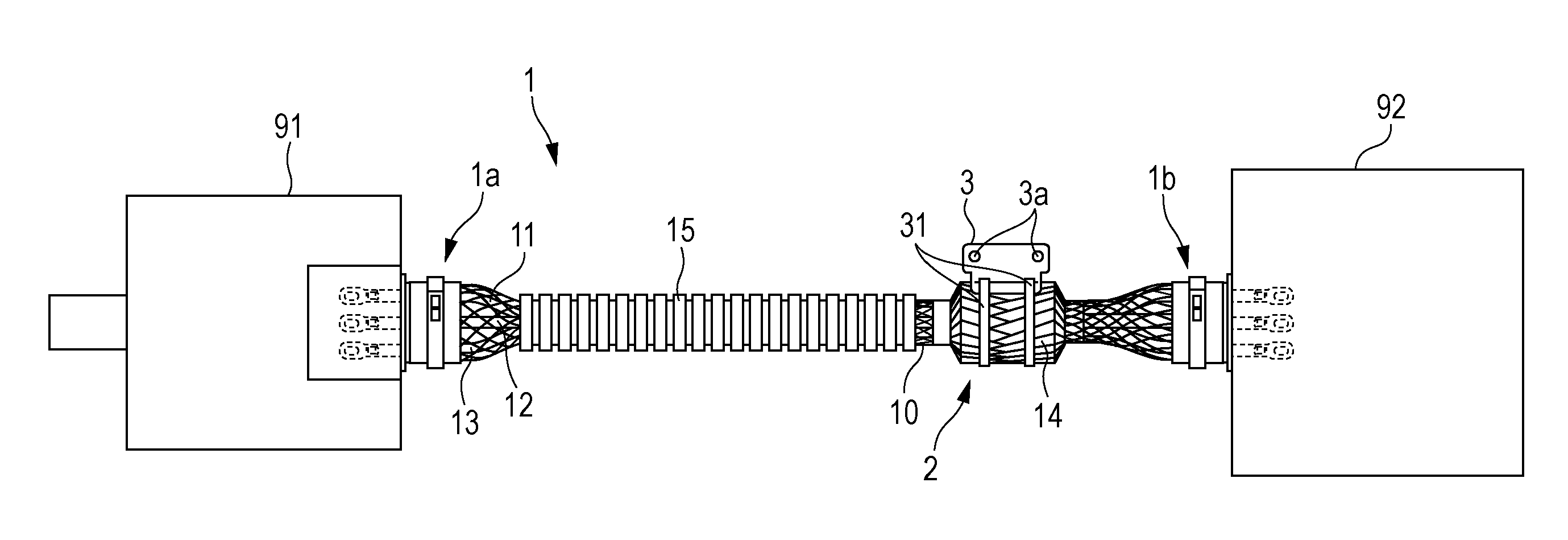
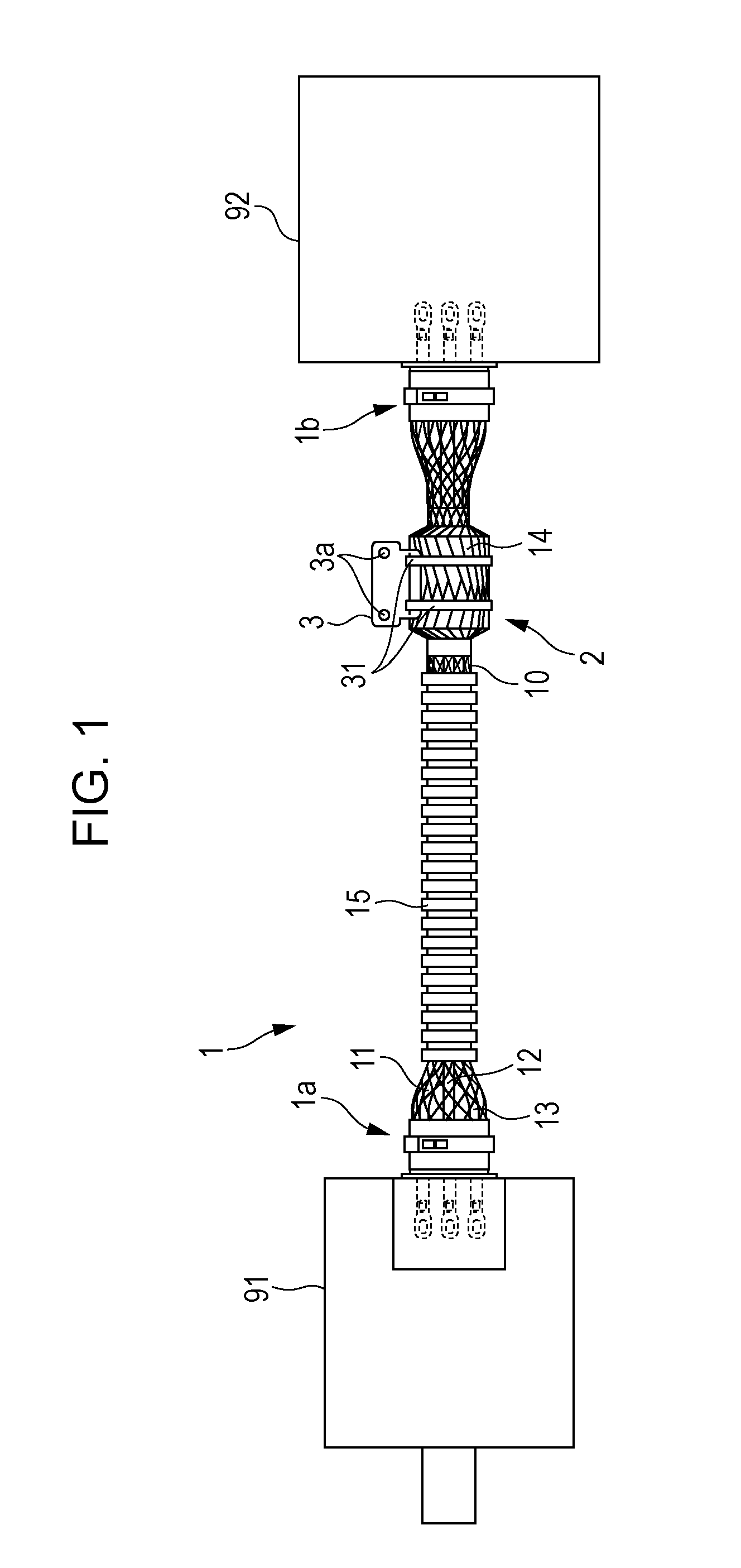
[0021]FIG. 1 is a schematic diagram of a wire harness 1 according to an embodiment of the present invention and an electric motor 91 and an inverter 92 connected together by the wire harness 1. The wire harness 1 is an example of a wiring member according to an aspect of the invention.

[0022]The wire harness 1 is installed in a vehicle including an electric motor as a source for driving the vehicle. The wire harness 1 is used to feed driving electric current, output from the inverter 92 after being subjected to pulse width modulation (PWM) control, to the electric motor 91, which is a driving source for generating force for driving the vehicle. The driving electric current contains harmonics caused by switching of a switching element such as a power transistor.

[0023]The wire harness 1 includes a first electric ...


PUM


Abstract

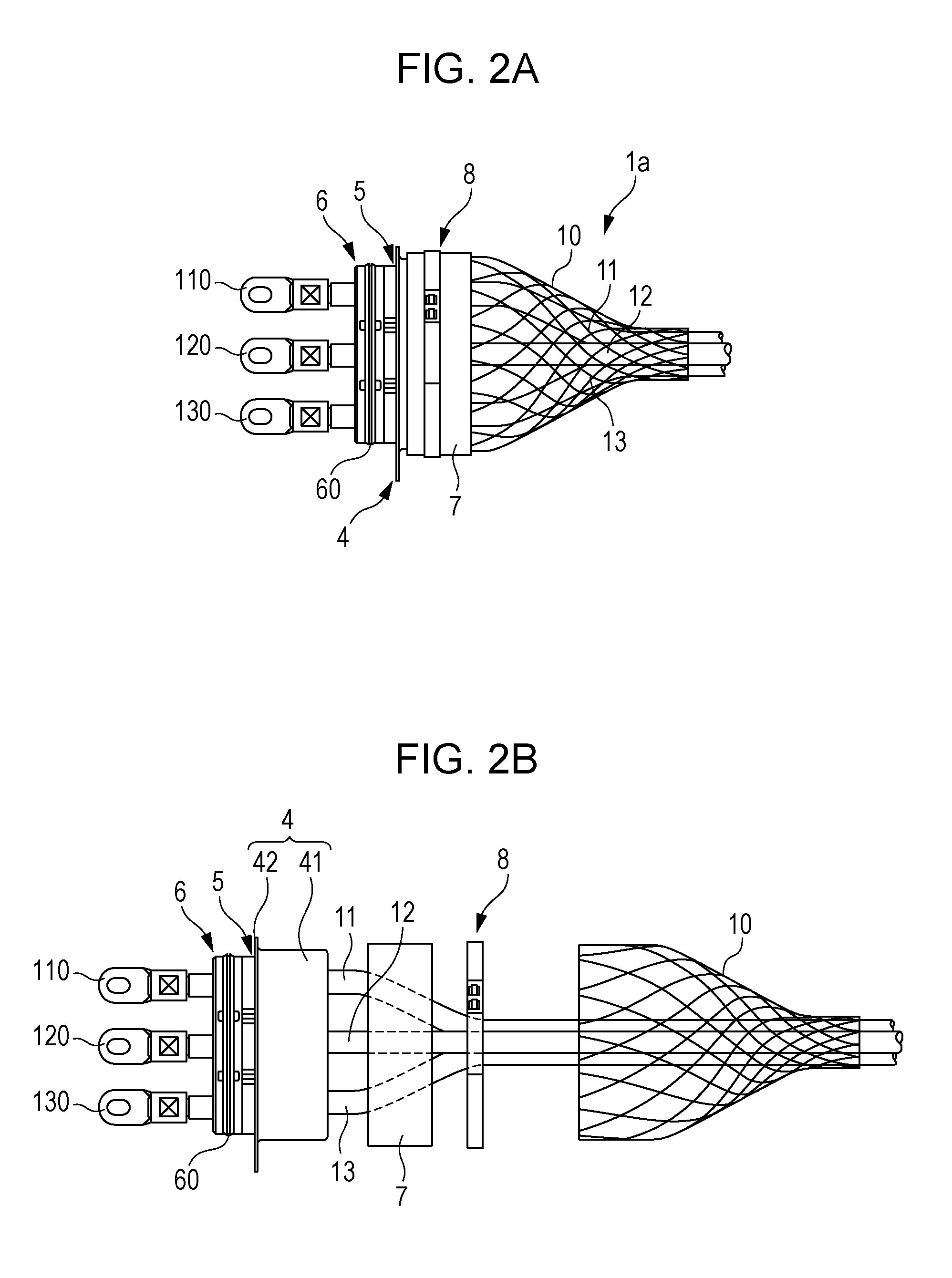
A wire harness includes first to third electric wires; a braid shield that covers the first to third electric wires; a tube-shaped electromagnetic wave absorber having a through hole that allows the first to third electric wires to be inserted therethrough, the electromagnetic wave absorber absorbing electromagnetic waves emitted from the first to third electric wires; and a resin tape and fasteners that fix the positions of the electromagnetic wave absorber and the braid shield relative to each other. The electromagnetic wave absorber is movable in an axial direction of the first to third electric wires relative to the first to third electric wires as a result of extension and contraction of the braid shield in the axial direction.

Description

[0001]The present application is based on Japanese patent application No. 2014-076249 filed on Apr. 2, 2014, the entire contents of which are incorporated herein by reference.BACKGROUND OF THE INVENTION[0002]1. Field of the Invention[0003]The present invention relates to wiring members, particularly to a wiring member including an electromagnetic wave absorber that reduces noise emitted from an electric wire.[0004]2. Description of the Related Art[0005]Some wiring members have been installed in vehicles including an electric motor as a source for driving the vehicle, that is, electric cars or hybrid cars, in order to connect the electric motor and an inverter together. Widely used examples of such wiring members include a wire harness obtained by binding multiple electric wires corresponding to different phases so that alternating currents having multiple different phases are provided to the electric motor (for example, see Japanese Unexamined Patent Application Publication No. 2011...

Claims


Application Information

Patent Timeline
Patent Type & Authority Applications(United States)
IPC IPC(8): H05K9/00B60L11/18
CPCB60L11/18H05K9/0066H01F2017/065H01F17/06B60L2270/145B60L2270/147B60L50/51Y02T10/70B60L50/50
Inventor IMAHORI, MASAAKIHAYAKAWA, YOSHIKAZUFUTATSUMORI, TAKAHIRO
Owner HITACHI METALS LTD
Learn More