Shielding of heat exchangers in columns

a heat exchanger and shielding technology, applied in lighting and heating apparatus, heating types, separation processes, etc., can solve the problems of insufficient heat recovery for use elsewhere, affecting the operation of liquid formed in the uppermost heat exchanger contacts the lower heat exchanger, etc., to achieve increased pressure drop and/or unstable operations, and cost-effective effects

Inactive Publication Date: 2005-04-26
UOP LLC
View PDF10 Cites 16 Cited by
  • Summary
  • Abstract
  • Description
  • Claims
  • Application Information

AI Technical Summary

Benefits of technology

[0012]One problem in locating two heat exchangers in a column to cool the vapors therein is that liquid formed in the uppermost heat exchanger contacts the lower heat exchanger and affects its operation. Descending liquid could, for example, change the heat transfer intended thus causing, for example, insufficient recovery of heat for use elsewhere. Additionally, descending liquid could flood and dam some or all of the vapor flow paths within the heat exchanger causing increased pressure drop and / or unstable operations. The subject invention provides a novel, cost effective solution for the foregoing problems. The subject invention may also be used to shield heat exchangers inside columns that exchange heat with a vapor phase wherever there is descending liquid, such as between two vapor / liquid contacting devices.

Problems solved by technology

One problem in locating two heat exchangers in a column to cool the vapors therein is that liquid formed in the uppermost heat exchanger contacts the lower heat exchanger and affects its operation.
Descending liquid could, for example, change the heat transfer intended thus causing, for example, insufficient recovery of heat for use elsewhere.
Additionally, descending liquid could flood and dam some or all of the vapor flow paths within the heat exchanger causing increased pressure drop and / or unstable operations.

Method used


Image

  • Shielding of heat exchangers in columns
  • Shielding of heat exchangers in columns
  • Shielding of heat exchangers in columns

Examples


Embodiment Construction

[0025]A column according to the subject invention can be designed as desired and be matched to any applications for which columns are conventionally used, such as for reactions, but typically for separating mixtures such as in various types of distillation columns.

[0026]A detailed description and various embodiments of the subject invention will now be given by reference to the accompanying drawings. The drawings are simplified schematic views, not to scale, only showing the components of the column necessary for an understanding of the invention. The drawings are presented to illustrate some embodiments of the invention and are not intended to limit the scope of the invention as set forth in the claims.

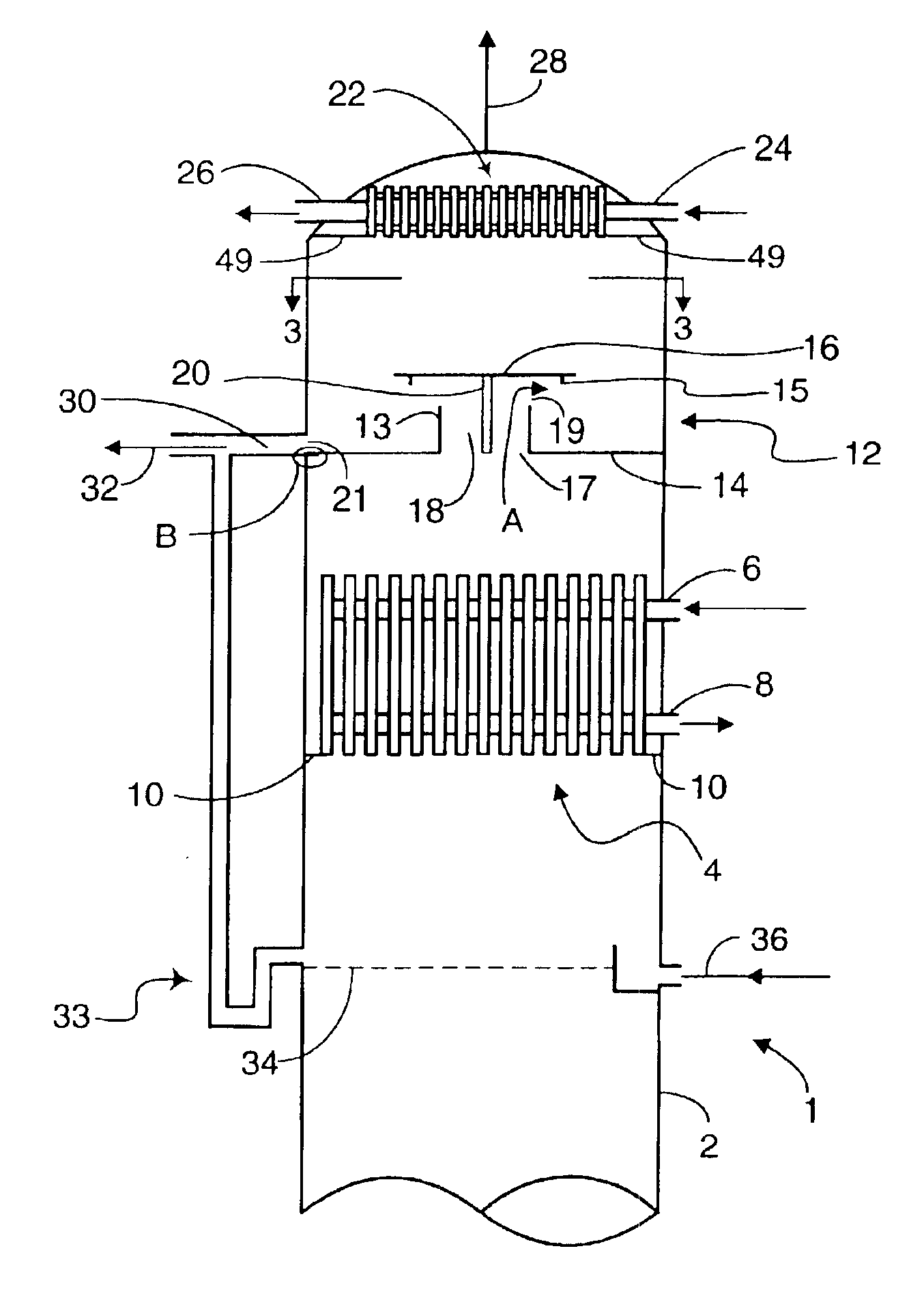
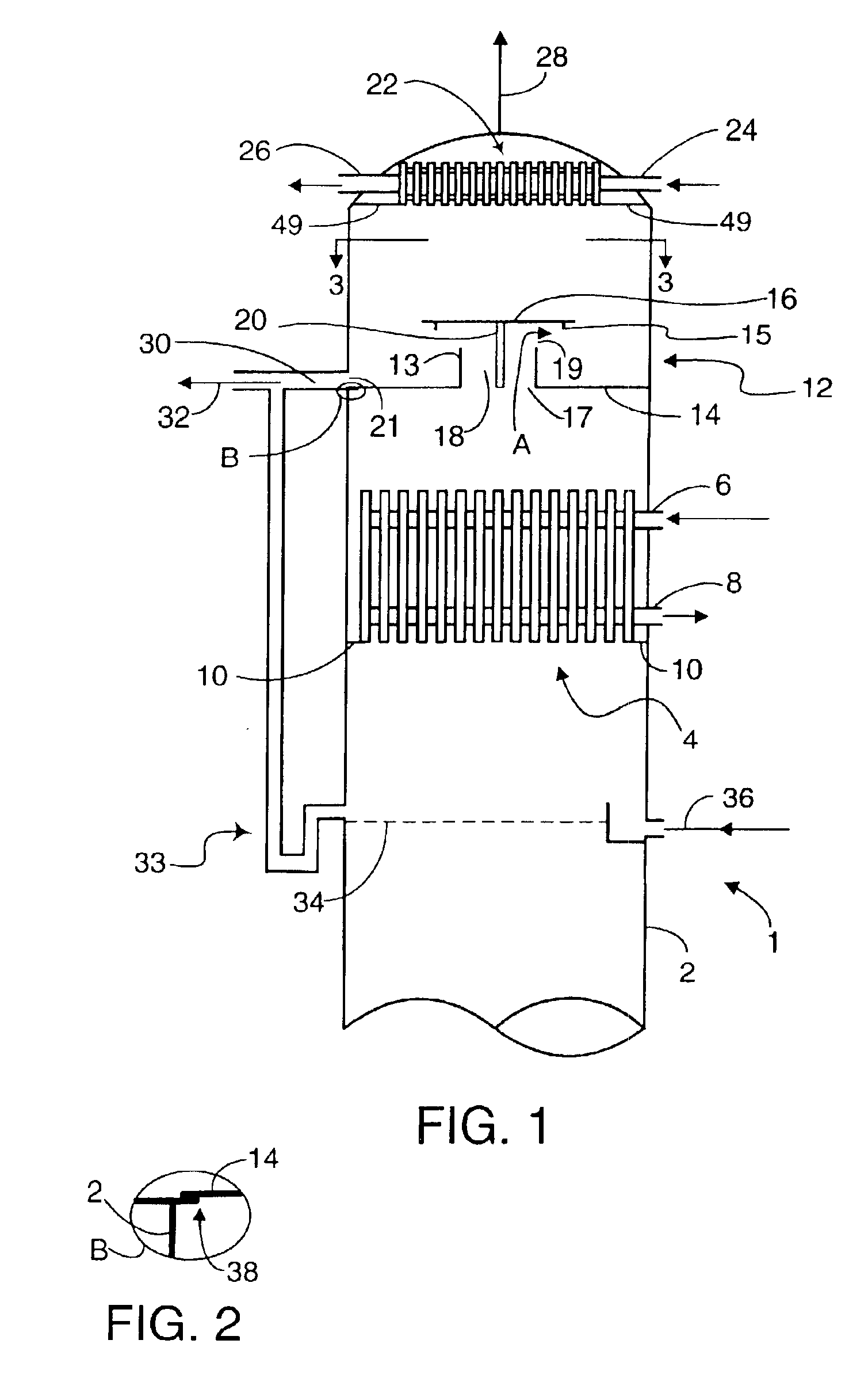
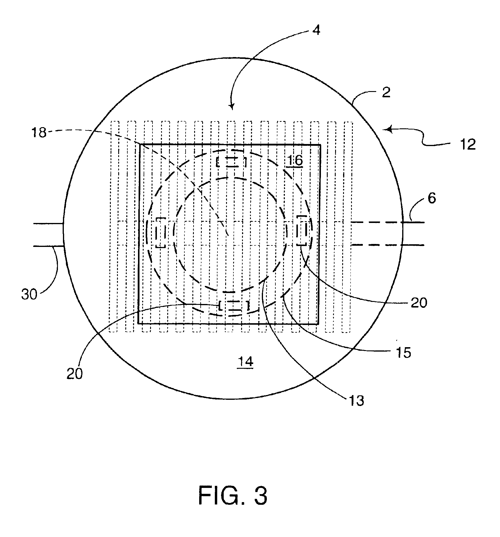
[0027]Referring now to FIG. 1, there is shown a top section of a column 1 having a shell 2. A first vapor phase ascends from an uppermost vapor / liquid contacting device 34 and passes through a first heat exchanger 4. The specific form and details of vapor / liquid contacting devices in...


PUM

PropertyMeasurementUnit
heataaaaaaaaaa
vapor/liquidaaaaaaaaaa
vapor phaseaaaaaaaaaa

Abstract

Disclosed is a method and an apparatus for exchanging heat in a column by passing a first vapor phase through a heat exchanger in the column to exchange heat with a first stream and produce a second vapor phase in the column. The second vapor phase is passed through a shielding device located above the heat exchanger and the shielding device prevents descending liquid from contacting the heat exchanger. The shielding device may be interposed between two heat exchangers in the column.

Description

BACKGROUND OF THE INVENTION[0001]1. Field of the Invention[0002]The invention relates to a process and apparatus for transferring heat in columns. The invention more specifically relates to shielding heat exchangers in columns from liquid.[0003]2. Description of Related Art[0004]Many industries such as petrochemical, chemical and petroleum refining use columns for separating mixtures. Such columns are typically cylindrical, vertically orientated vessels wherein rising vapor and descending liquid come into contact, transfer components, separate, and pass respectively towards the top and bottom sections of the column. Frequently, columns contain vapor-liquid contacting devices to enhance the contacting and separation of the vapor and liquid phases. Examples of vapor-liquid contacting devices include trays and packings. Many of these vapor / liquid contacting devices have a wide variety of designs. For example, tray types of vapor / liquid contacting devices include bubble cap, sieve, valv...

Claims


Application Information

Patent Timeline
Patent Type & Authority Patents(United States)
IPC IPC(8): B01D5/00B01D3/14B01D3/16F28D9/00F28B9/00F28B9/08
CPCB01D3/16B01D3/166F28B9/08F28D9/0093B01D5/0063Y10S165/197
Inventor TAGAMOLILA, CONSTANTE P.O'DRISCOLL, F. JOSEPH
Owner UOP LLC
Why Eureka
Try Eureka