Fishing reel

a reel and reel body technology, applied in the field of fishing reels, can solve the problems of reducing the voltage to be supplied to the controller and the voltage to be controlled, the electric component cannot be normally operated, and the voltage of the control signal is reduced

Active Publication Date: 2017-07-27
SHIMANO INC
View PDF0 Cites 6 Cited by
  • Summary
  • Abstract
  • Description
  • Claims
  • Application Information

AI Technical Summary

Benefits of technology

[0007]It is an object of the present disclosure to prevent an unstable operation of an electric component used for a control purpose in a fishing reel that causes the electric component to operate with electric power generated by braking, even when the rotational velocity of a spool is low and the voltage of the generated electric power is low.
[0009]The fishing reel causes the voltage booster circuit to increase the voltage supplied to the electric component. With this configuration, the electric component can be prevented from operating in an unstable manner even when the voltage of the generated electric power is low.
[0010]The voltage booster circuit in the fishing reel can increase the voltage of a control signal outputted from the spool controller. According to this configuration, a voltage of the control signal, which is liable to be affected by a reduction in a voltage and greatly affects a control action per se, is increased. Hence, the electric component can be prevented from operating in an unstable manner, and furthermore, the control action per se, affected by the control signal, can be prevented from being performed in an unstable manner.
[0011]The spool brake can include a magnet and a plurality of coils. The magnet can be coupled to the spool in a unitarily rotatable state, and can have a plurality of magnetic poles aligned in a circumferential direction. The plurality of coils can be disposed on an outer peripheral side of the magnet, and can be aligned in a rotational direction of the spool. According to this construction, electric power can be easily generated by the rotation of the spool.
[0014]Overall, according to the present disclosure, the electric component can be prevented from operating in an unstable manner even when the voltage of generated electric power is low.

Problems solved by technology

In a well-known mechanism for dynamic braking, it is concerned that when the rotational velocity of the spool gets slow in the latter phase of casting, the voltage of generated electric power lowers and this results in reduction in voltage to be supplied to the controller and reduction in voltage of a control signal (e.g., duty cycle for spool braking), whereby an electric component cannot be normally operated.

Method used


Image

  • Fishing reel
  • Fishing reel
  • Fishing reel

Examples


Embodiment Construction

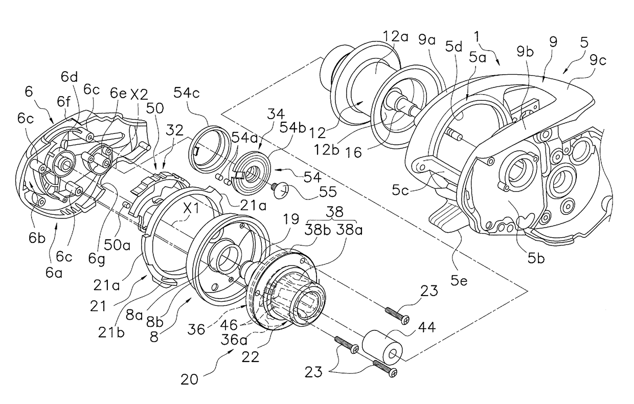
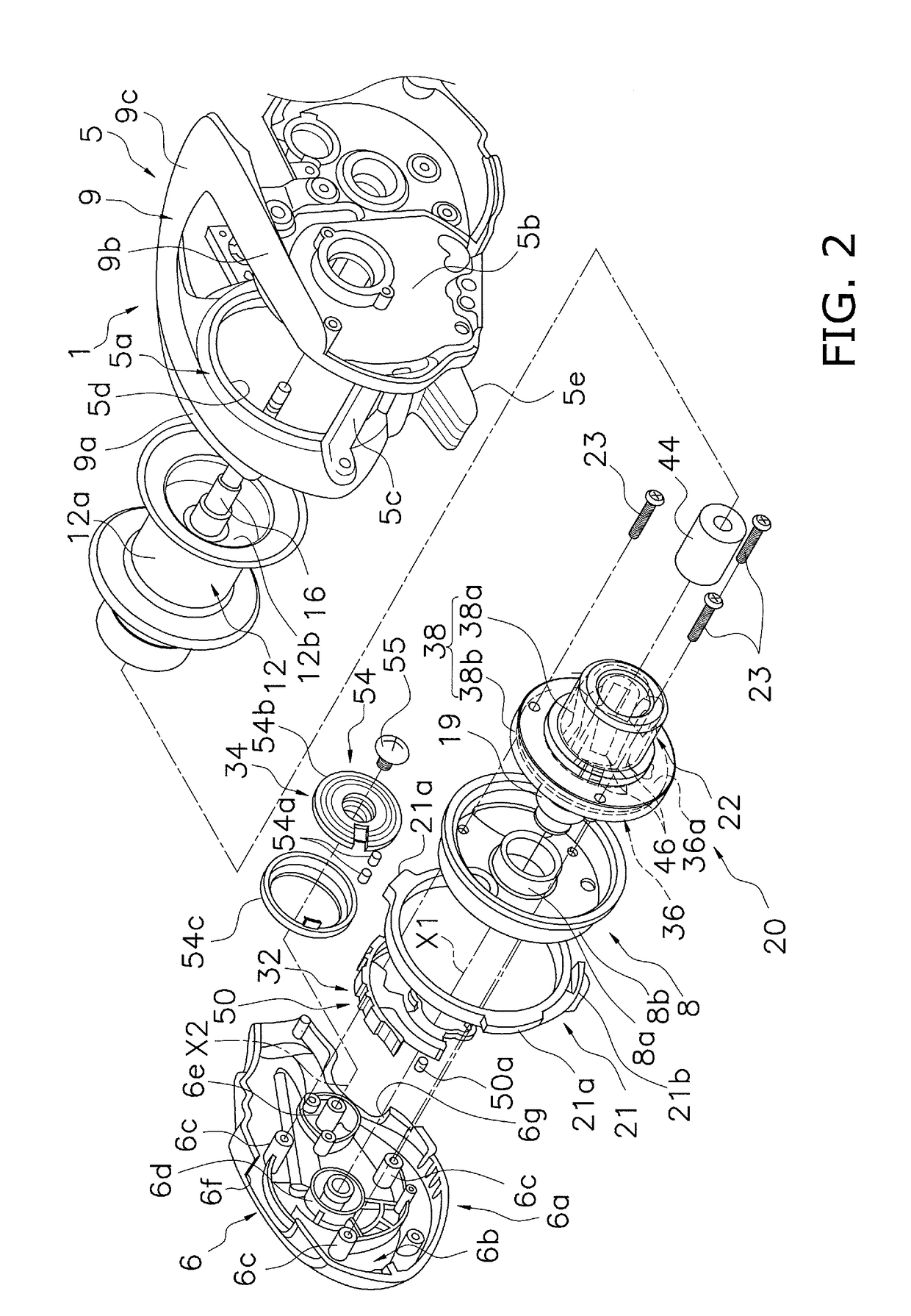
[0026]As shown in FIGS. 1, 2, 3 and 7, a dual-bearing reel 100 is a compact bait-casting reel and is provided as a fishing reel according to a preferred embodiment of the present disclosure. The dual-bearing reel 100 includes a reel unit 1, a handle 2, a spool 12, a spool brake 22 (see FIGS. 2 and 7), an electric component 18 (see FIG. 7) including a spool controller 25, a rotation detector 31 (see FIG. 7) and a voltage booster circuit 41 (see FIG. 7).

[0027]The reel unit 1 includes a frame 5, a first side cover 6 and a second side cover 7. The frame 5 is an integrally formed component. The first side cover 6 is disposed laterally to the frame 5 on the opposite side of the handle 2. The second side cover 7 is disposed laterally to the frame 5 on the same side as the handle 2.

[0028]As shown in FIG. 2, the frame 5 includes a first side plate 5a, a second side plate 5b, a plurality of coupling portions 5c and a thumb rest 9. The first side plate 5a is disposed on the opposite side of th...


PUM


Abstract

A fishing reel forwardly releases a fishing line and includes a reel unit, a spool, a spool brake, an electric component, and a voltage booster circuit. The spool is rotatably supported by the reel unit. The spool brake generates an electric power upon a rotation of the spool, and applies a brake force to brake the spool using the electric power when the spool is rotated. The electric component operates using the electric power generated by the spool brake. The voltage booster circuit increases a voltage supplied to the electric component.

Description

CROSS-REFERENCE TO RELATED APPLICATIONS[0001]This application claims priority to Japanese Patent Application No. 2016-010628 filed on Jan. 22, 2016, the entirety of which is hereby incorporated by reference in its entirety.BACKGROUND[0002]1. Technical Field[0003]The present disclosure relates to a fishing reel, and particularly to a fishing reel that generates electric power by rotation of a spool and brakes the spool with the generated electric power.[0004]2. Background Information[0005]As a type of fishing reel, there has been known a dual-bearing reel that performs dynamic braking by generating electric power and braking a spool with the generated electric power and simultaneously controls a braking force with the generated electric power during a casting in which the spool is rotated at high speed in a fishing line releasing direction (see e.g., Japan Laid-open Patent Application Publication No. 2004-208630). In the well-known dual-bearing reel, a spool brake includes a magnet t...

Claims


Application Information

Patent Timeline
Patent Type & Authority Applications(United States)
IPC IPC(8): A01K89/0155
CPCA01K89/01555A01K89/015A01K89/02F16D65/14F16D2121/20A01K89/056A01K89/045A01K89/01931
Inventor NUMATA, FUMIHIDETAKI, NORIKAZUISHIKAWA, YUICHIRONIITSUMA, AKIRA
Owner SHIMANO INC
Why Eureka
Try Eureka