Voltage regulator

a voltage regulator and voltage technology, applied in the direction of dc-dc conversion, pulse characteristics measurement, power conversion systems, etc., can solve the problem of excessive current flow, achieve the effect of preventing unstable operation of the voltage regulator and suppressing the fluctuation of output voltag

Active Publication Date: 2016-11-24
MITSUMI ELECTRIC CO LTD
View PDF0 Cites 6 Cited by
  • Summary
  • Abstract
  • Description
  • Claims
  • Application Information

AI Technical Summary

Benefits of technology

[0012]The present invention has been made in view of the above-mentioned problems, and provides a voltage regulator configured to suppress a fluctuation in output voltage even when a power supply voltage fluctuates, thereby realizing stable operation thereof.
[0015]The voltage regulator according to the present invention can suppress a fluctuation in output voltage even when the power supply fluctuates, by increasing the current of the error amplifier circuit. Further, the voltage regulator is configured not to respond to a small fluctuation in output voltage that is caused when the power supply voltage or the like slightly fluctuates, but to cause an excessive current to flow through the error amplifier circuit when the output voltage largely fluctuates due to a large fluctuation in power supply voltage or the like. In this manner, unstable operation of the voltage regulator can be prevented.

Problems solved by technology

Further, the voltage regulator is configured not to respond to a small fluctuation in output voltage that is caused when the power supply voltage or the like slightly fluctuates, but to cause an excessive current to flow through the error amplifier circuit when the output voltage largely fluctuates due to a large fluctuation in power supply voltage or the like.

Method used


Image

  • Voltage regulator
  • Voltage regulator
  • Voltage regulator

Examples


first embodiment

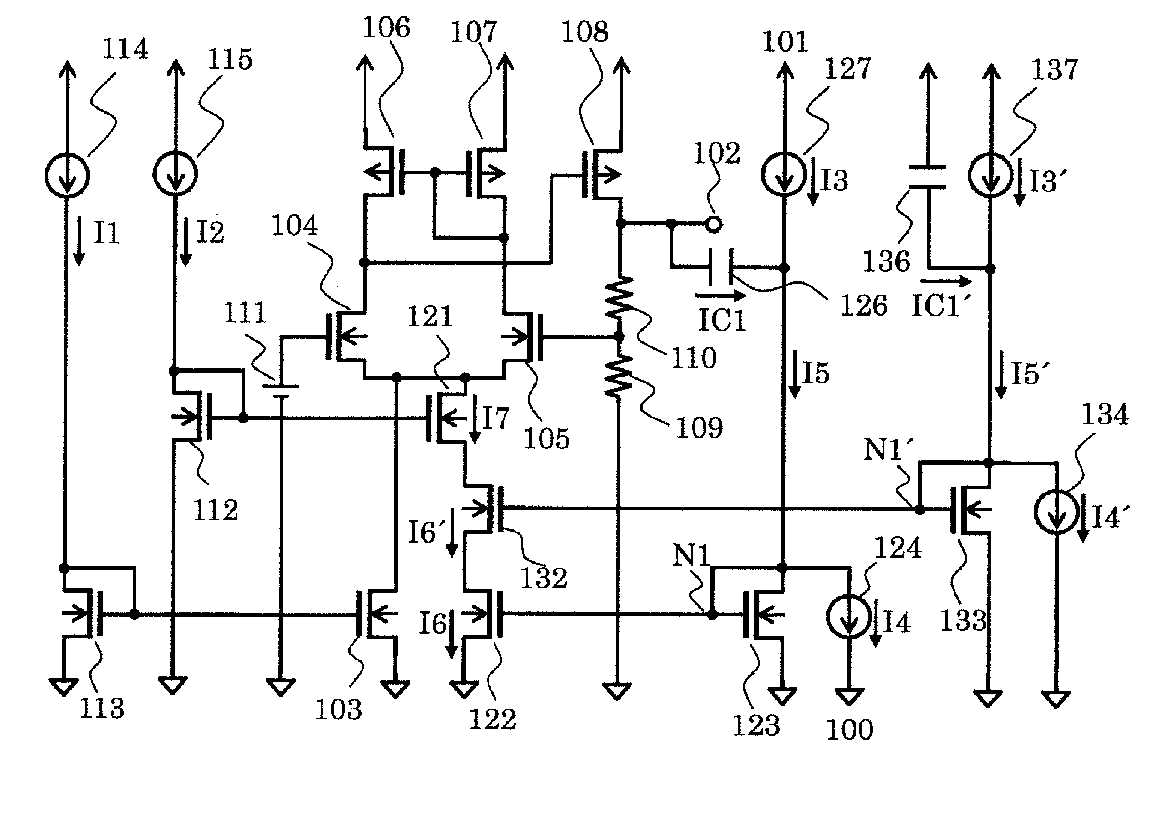
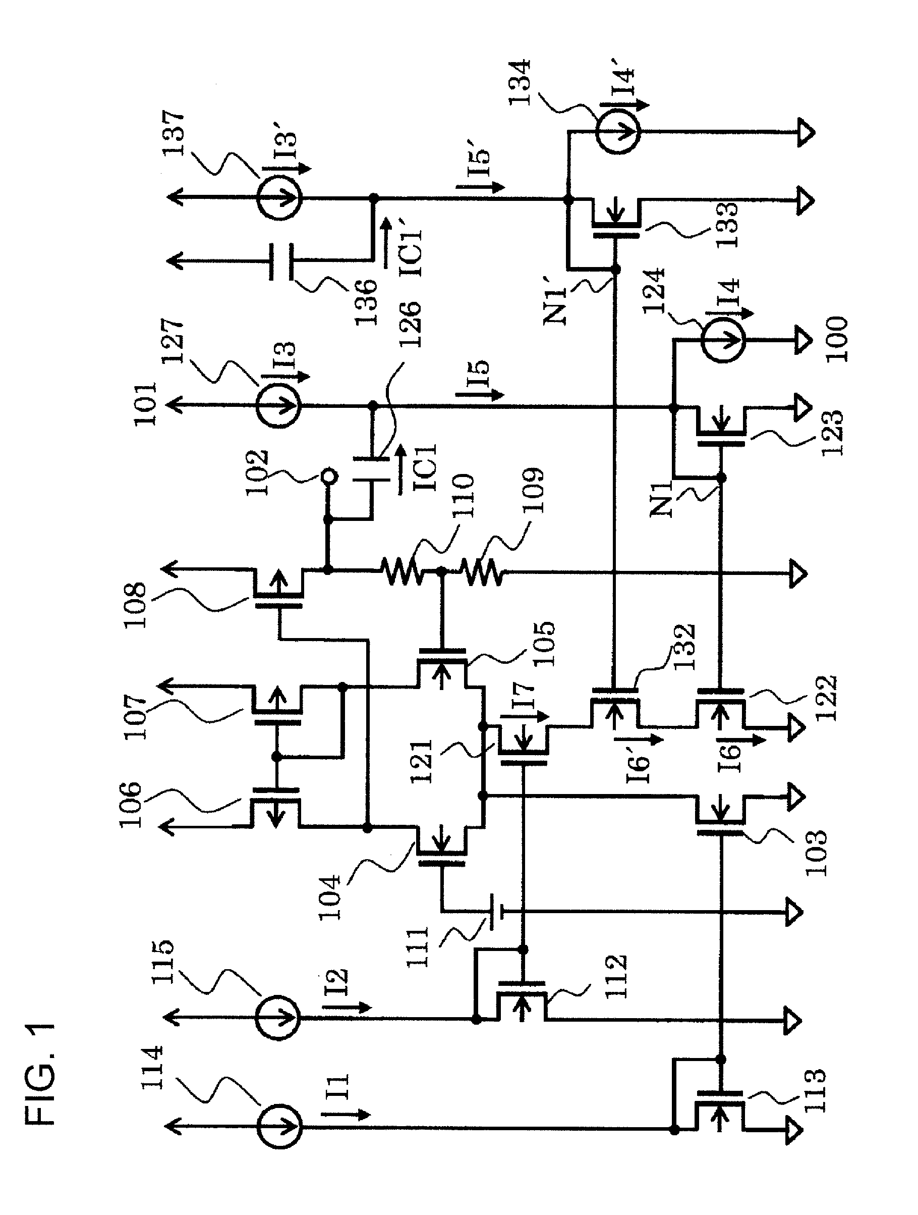
[0020]FIG. 1 is a circuit diagram of a voltage regulator according to a first embodiment of the present invention.

[0021]The voltage regulator of the first embodiment includes PMOS transistors 106, 107, and 108, NMOS transistors 103, 104, 105, 112, 113, 121, 122, 123, 132, and 133, resistors 109 and 110, capacitors 126 and 136, a reference voltage circuit 111, constant current circuits 114, 115, 127, 124, 137, and 134, a ground terminal 100, a power supply terminal 101, and an output terminal 102.

[0022]The PMOS transistors 106 and 107 and the NMOS transistors 103, 104, and 105 form an error amplifier circuit. The constant current circuits 124, 127, 137, and 134, the capacitors 126 and 136, and the NMOS transistors 123, 122, 133, 132, and 121 form a control circuit. The capacitor 126 and the constant current circuits 124 and 127 form an overshoot detection circuit configured to detect overshoot of an output voltage Vout. The capacitor 136 and the constant current circuits 134 and 137 ...

second embodiment

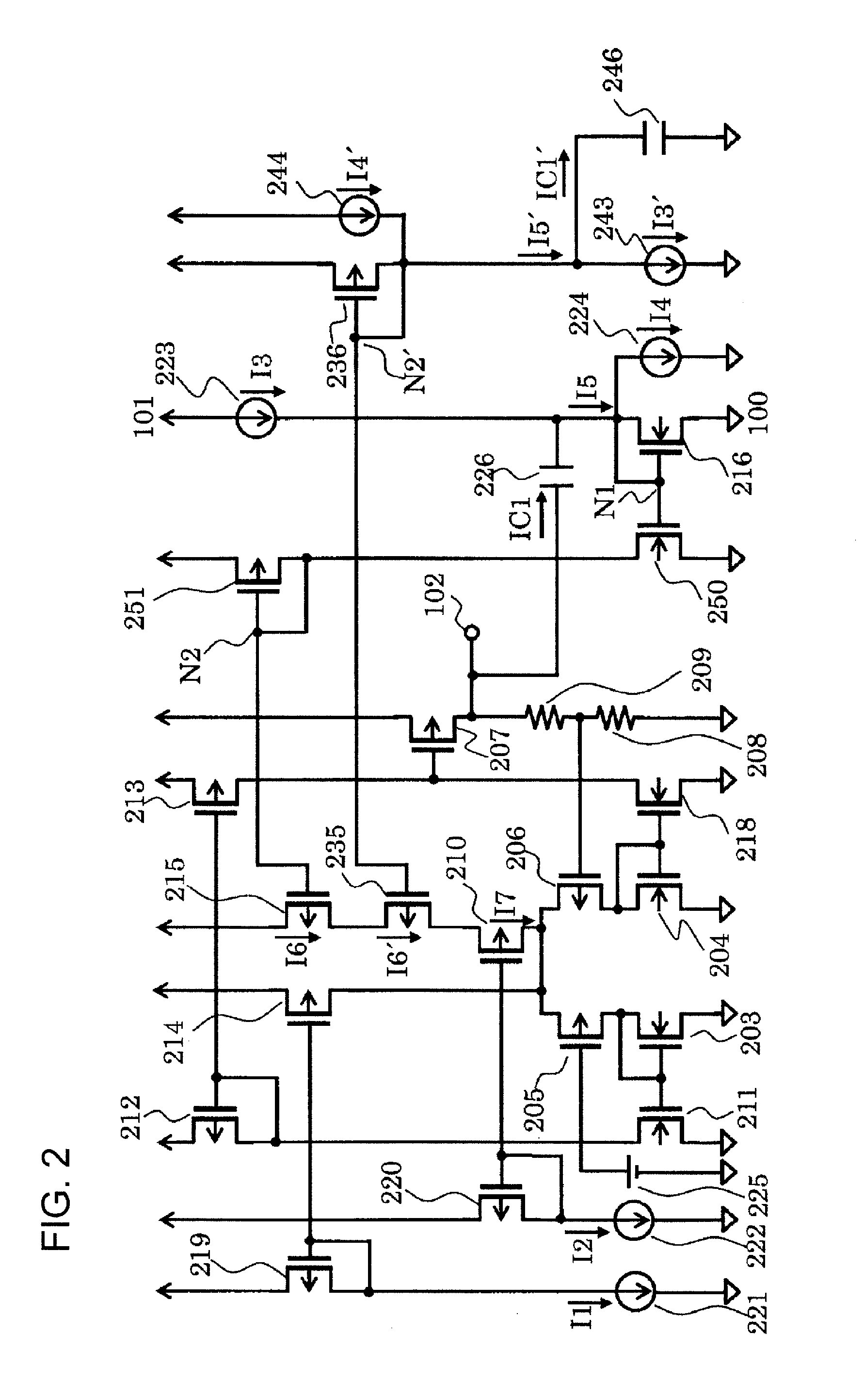
[0031]FIG. 2 is a circuit diagram of a voltage regulator according to a second embodiment of the present invention.

[0032]The voltage regulator of the second embodiment includes PMOS transistors 205, 206, 207, 210, 212, 213, 214, 215, 219, 220, 235, 236, and 251, NMOS transistors 203, 204, 211, 216, 218, and 250, resistors 208 and 209, capacitors 226 and 246, a reference voltage circuit 225, constant current circuits 221, 222, 223, 224, 243, and 244, a ground terminal 100, a power supply terminal 101, and an output terminal 102. The PMOS transistors 205, 206, 212, 213, and 214 and the NMOS transistors 203, 204, 211, and 218 form an error amplifier circuit. The constant current circuits 224, 223, 244, and 243, the capacitors 226 and 246, the PMOS transistors 210, 215, 235, 236, and 251, and the NMOS transistors 216 and 250 form a control circuit. The capacitor 226 and the constant current circuits 223 and 224 form an overshoot detection circuit configured to detect overshoot of an out...


PUM


Abstract

Provided is a voltage regulator configured to suppress a fluctuation in output voltage even when a power supply voltage fluctuates, thereby realizing stable operation thereof. The voltage regulator includes a control circuit including a first input terminal connected to a drain of an output transistor, a second input terminal connected to a power supply terminal, an overshoot detection circuit connected to the first input terminal, and a power supply voltage detection circuit connected to the second input terminal, and being configured to cause a boost current to flow through an error amplifier circuit when an output voltage and a power supply voltage largely fluctuate with respect to a predetermined voltage.

Description

RELATED APPLICATIONS[0001]This application claims priority under 35 U.S.C. §119 to Japanese Patent Application No. 2015-103910 filed on May 21, 2015, the entire content of which is hereby incorporated by reference.BACKGROUND OF THE INVENTION[0002]1. Field of the Invention[0003]The present invention relates to a voltage regulator capable of suppressing a fluctuation in output voltage even when a power supply fluctuates.[0004]2. Description of the Related Art[0005]A related-art voltage regulator is described. FIG. 3 is a circuit diagram for illustrating the related-art voltage regulator.[0006]The related-art voltage regulator includes PMOS transistors 106, 107, 108, 301, 302, and 303, NMOS transistors 103, 104, 105, 304, 305, 306, 307, and 308, resistors 109, 110, and 309, a capacitor 310, a ground terminal 100, a power supply terminal 101, and an output terminal 102.[0007]The PMOS transistors 301, 302, and 303, the NMOS transistors 305, 306, and 308, and the resistor 309 form a bias ...

Claims


Application Information

Patent Timeline
Patent Type & Authority Applications(United States)
IPC IPC(8): G05F3/24G05F3/26
CPCG05F3/262G05F3/24G05F1/565G01R15/16G01R29/02H02M3/156
Inventor TOMIOKA, TSUTOMUSUGIURA, MASAKAZU
Owner MITSUMI ELECTRIC CO LTD
Why Eureka
Try Eureka