Heat exchange apparatus for circulating fluidized bed boilers

a technology of fluidized bed boilers and heat exchange apparatuses, which is applied in the direction of fluidised bed apparatus, lighting and heating apparatus, combustion types, etc., can solve the problems of corroding, exhaust gas, abrasion of the tube, etc., and achieve the effect of improving the expandability of external heat exchangers

Inactive Publication Date: 2016-12-29
KOREA ELECTRIC POWER CORP +1
View PDF6 Cites 6 Cited by
  • Summary
  • Abstract
  • Description
  • Claims
  • Application Information

AI Technical Summary

Benefits of technology

[0011]The present invention is directed to a heat exchange apparatus for circulating fluidized bed boilers capable of solving unstable operation of a power generation system caused by a control valve and further improving expandability of external heat exchangers.

Problems solved by technology

However, corrosion of the tube by an exhaust gas and abrasion of the tube by a flow medium may be caused when the tube is disposed on the combustion furnace.
However, there are cases in that the flow medium flowing into the external heat exchanger may stay in the control valve, or the control valve may be damaged by the flow medium having a high temperature greater than or equal to 800° C. As a result, the power generation system cannot have a normal output, and an operation of the power generation system may also be stopped when the control valve is seriously damaged.
Therefore, costs required to replace, repair and maintain a portion of the control valve may increase.
Also, when the loop seal and the external heat exchanger are separately run, the lack of an available space may be caused, and only one external heat exchanger may be run in one cyclone.
As result, there are spatial constraints on an increase in the number of external heat exchangers, that is, an expansion of the external heat exchangers.

Method used


Image

  • Heat exchange apparatus for circulating fluidized bed boilers
  • Heat exchange apparatus for circulating fluidized bed boilers
  • Heat exchange apparatus for circulating fluidized bed boilers

Examples


Embodiment Construction

[0031]A heat exchange apparatus for circulating fluidized bed boilers according to one exemplary embodiment of the present invention will be described in detail below with reference to the accompanying drawings. While the present invention is shown and described in connection with exemplary embodiments thereof, it will be apparent to those skilled in the art that various modifications can be made without departing from the scope of the invention.

[0032]Unless specifically stated otherwise, all the technical and scientific terms used in this specification have the same meanings as what are generally understood by a person skilled in the related art to which the present invention belongs. In general, the nomenclatures used in this specification and the experimental methods described below are widely known and generally used in the related art.

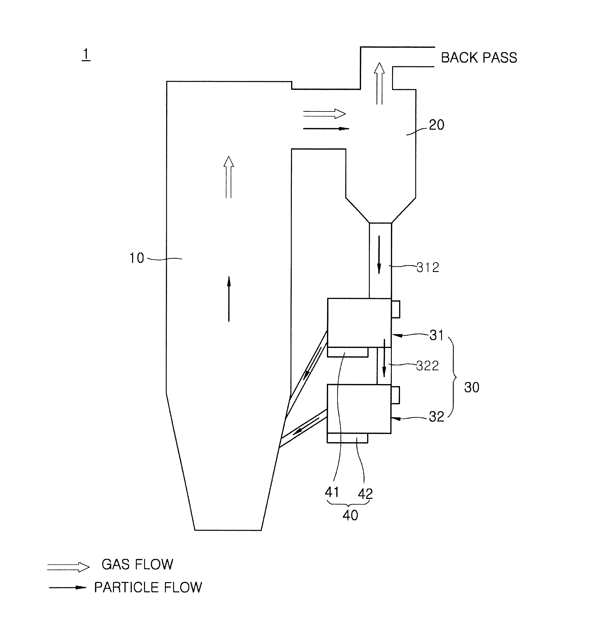
[0033]FIG. 1 is a concept diagram schematically showing a heat exchange apparatus for circulating fluidized bed boilers according to one exemplar...


PUM


Abstract

A heat exchange apparatus for circulating fluidized bed boilers is disclosed. The heat exchange apparatus for circulating fluidized bed boilers includes a particle separator configured to separate an exhaust gas and a flow medium discharged from a combustion furnace, an external heat exchanger into which the flow medium collected in the particle separator flows and which is configured to heat a heat transfer medium by heat exchange with the flow medium, and a flow control unit installed at the external heat exchanger and configured to supply air to a flow path of the flow medium and to regulate an internal temperature of the external heat exchanger under the control of a flow direction and a flow quantity of the flow medium.

Description

CROSS-REFERENCE TO RELATED APPLICATION[0001]This application claims priority to and the benefit of Korean Patent Application No. 10-2015-0092492, filed on Jun. 29, 2015, the disclosure of which is incorporated herein by reference in its entirety.BACKGROUND[0002]1. Field of the Invention[0003]The present invention relates to a heat exchange apparatus for circulating fluidized bed boilers, and more particularly, to a heat exchange apparatus for circulating fluidized bed boilers capable of controlling a quantity of a flow medium flowing into an external heat exchanger.[0004]2. Discussion of Related Art[0005]Various heat exchangers such as a membrane wall tube provided in a combustion furnace, a wing wall tube provided at an upper portion of the combustion furnace, a platen tube, and the like are applied to a circulating fluidized bed boiler to recover the heat of combustion of coal. However, corrosion of the tube by an exhaust gas and abrasion of the tube by a flow medium may be caused...

Claims


Application Information

Patent Timeline
Patent Type & Authority Applications(United States)
IPC IPC(8): F28D13/00
CPCF28D13/00F28F27/02F23N3/00F23C10/26F23C2206/10F23C10/00
Inventor PARK, KYOUNG ILLEE, TAE HEEKIM, DONG WONLEE, JONG MIN
Owner KOREA ELECTRIC POWER CORP
Why Eureka
Try Eureka