Freezing/cooling device

A cooling device and fan technology, which is used in household refrigeration devices, defrosting, household appliances, etc., can solve the problems of reduced cooling capacity and increased pressure loss of unit coolers, and achieve the effect of uncomplicated structure and effective heating

Active Publication Date: 2015-10-14
MITSUBISHI ELECTRIC CORP
View PDF5 Cites 0 Cited by
  • Summary
  • Abstract
  • Description
  • Claims
  • Application Information

AI Technical Summary

Problems solved by technology

If these frosts are left in this way, the wind passing through the evaporator and fan guard will increase the pressure loss under the influence of frost, resulting in a significant reduction in the cooling capacity of the unit cooler

Method used


Image

  • Freezing/cooling device
  • Freezing/cooling device
  • Freezing/cooling device

Examples


Embodiment Construction

[0030] Hereinafter, embodiments of the present invention will be described with reference to the drawings.

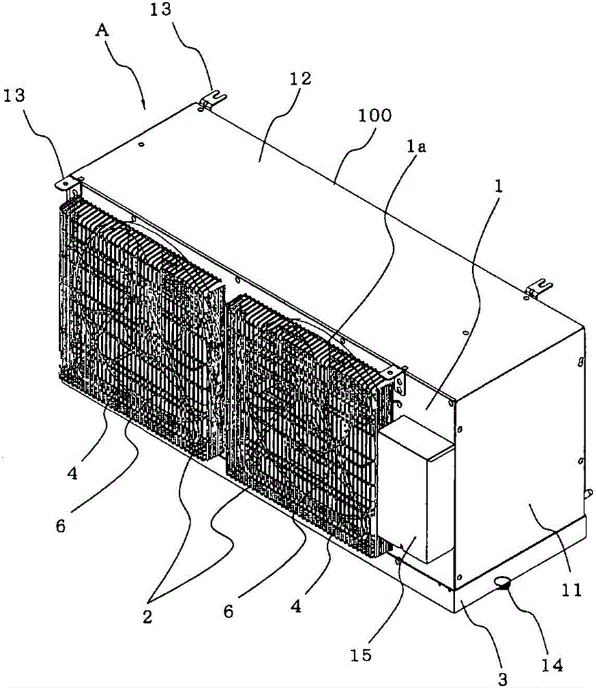
[0031] figure 1 It is an external perspective view of the freezing / cooling device (freezing device, cooling device (hereinafter referred to as unit cooler A)) according to the embodiment of the present invention viewed obliquely from above. refer to figure 1 The structure and operation of the unit cooler A will be described. The unit cooler A is installed in, for example, a freezer or a refrigerator, and cools the inside of the refrigerator. include figure 1 In each of the following drawings, the size relationship of each component may be different from the actual product. In addition, in each figure, what is attached|subjected with the same code|symbol represents the same or an equivalent member, and this is the same in the whole specification.

[0032] [Structure of Unit Cooler A]

[0033] First, the structure of the unit cooler A will be described. The unit...


PUM


Abstract

The present invention provides a freezing / cooling device which is uncomplicated in structure, and can raise safety and efficiently remove frost. Each fan shield heater (4) in a unit cooler (A) comprises a first straight line portion (41) and a straight line portion which is formed in a manner of surrounding a part of the periphery of a central hub portion of a fan (6) of an air blower. The first straight line portion is mounted under a fan shield (2) and straightly extends along the width direction of the fan shield (2).

Description

technical field [0001] This invention relates to the freezing / cooling apparatus which cools the inside of a freezer, a refrigerator, etc., for example. Background technique [0002] Conventionally, for example, there is a freezing / cooling device (hereinafter referred to as a unit cooler) that cools the inside of a freezer, a refrigerator, or the like. Many of these unit coolers have a main body case formed with a suction port and an air outlet, an evaporator provided at a position facing the air outlet of the main body case, and a blower provided in the main body case. The evaporator cools the air by evaporating the refrigerant supplied by the action of the externally mounted compressor. The air blower supplies the air in the cooling target space such as a warehouse to the evaporator, and supplies the air cooled by the evaporator to the cooling target space. In addition, in some unit coolers, the air outlet of the main body box is provided with a fan guard to prevent forei...

Claims


Application Information

Patent Timeline
Patent Type & Authority Patents(China)
IPC IPC(8): F25D21/08
Inventor 藤本肇篠原郁子松浦考伦中林敬幸
Owner MITSUBISHI ELECTRIC CORP
Why Eureka
Try Eureka