Seal component manufacturing method

A manufacturing method and technology for sealing parts, applied in the direction of final product manufacturing, sealing/supporting device, sustainable manufacturing/processing, etc., can solve the adverse effect of sealing gasket 2, damage to substrate 1, taking a long time, etc. problem, to achieve the effect that the structure of the metal mold is not complicated and the structure of the metal mold is simplified

Active Publication Date: 2013-11-06
NOK CORP
View PDF6 Cites 0 Cited by
  • Summary
  • Abstract
  • Description
  • Claims
  • Application Information

AI Technical Summary

Problems solved by technology

[0009] However, according to the molding method as described above, for example, when the sealing lip 2b of the gasket 2 is in close contact with the bottom surface of the groove formed in the separator, the burrs 2c formed by the exhaust grooves 104b, 105b are not accommodated in the spacer. In the above-mentioned groove, it has a bad influence on the sealing performance of the gasket 2, and it becomes the cause of the distortion of the base material 1. Therefore, such burrs 2c must be removed after the gasket 2 is formed.
In particular, when the gasket 2 is provided on both surfaces of the base material 1, since the burr 2c exists on both surfaces of the base material 1, it takes a long time to remove the burr, and it is difficult to remove the burr. cause substrate 1 damage

Method used


Image

  • Seal component manufacturing method
  • Seal component manufacturing method
  • Seal component manufacturing method

Examples


Embodiment Construction

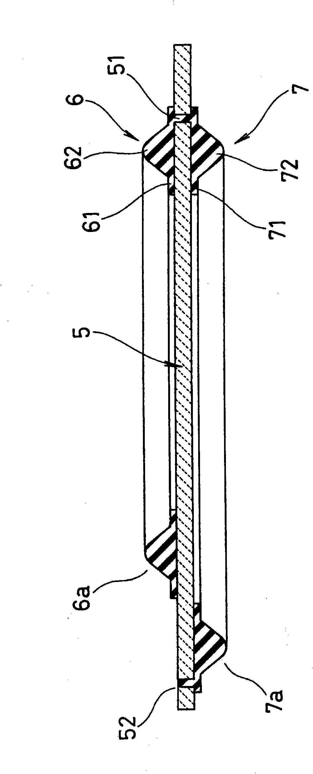
[0047] Next, preferred embodiments of the method of manufacturing a sealing member according to the present invention will be described with reference to the drawings. first, figure 1 It is a cross-sectional view showing a sealing member in which gaskets having different elongated shapes are integrally formed on both surfaces of a base material.

[0048] figure 1 The sealing member shown in is used as a sealing member for each cell in a fuel cell, and sealing gaskets 6 and 7 having different extended shapes (lip lines) are integrally formed on both surfaces of a base material 5 .

[0049] Specifically, the substrate 5 is made of, for example, a synthetic resin film, a carbon plate, ceramics, a metal porous material, or a thin metal plate, but is not particularly limited. The gaskets 6 and 7 are made of rubber material or a synthetic resin material having rubber-like elasticity, and are connected in a ring shape (endless shape) along the vicinity of the outer periphery of t...


PUM


Abstract

A method of manufacturing a seal part having gaskets formed integrally on opposite sides of a base material (5) having a film-like, sheet-like, or a plate-like shape. The gaskets can be formed on opposite sides of the base material (5) without forming burrs on the surfaces of the base material (5) . A first cavity (14) and a second cavity (15) are interconnected through a first communicating hole (51) open in the base material (5). The first cavity (14) is formed between the base material (5) and a first split mold (11) butted to one side of the base material (5) and having a molding material-supplying gate (11b) open therein (in the firstsplit mold (11)), and the second cavity (15) is formed between the base material (5) and a second split mold (12) butted to the other side of the base material (5). In the first split mold (11), there are formed a first air vent hole (11c) open in that portion of the first cavity (14) into which a molding material merges, and a second air vent hole (11d) open at the position of a second communicating hole (52) which is open in the base material (5) and is located in that portion of the second cavity (15) into which the molding material merges. The first and second air vent holes (11c, 11d) are located separated from the surface of the basematerial (5).

Description

technical field [0001] The present invention relates to fuel cell seals used to seal passages of fuel cell units formed in fuel cell stacks, etc., which are integrally formed in a film, sheet or plate-shaped base frame and are made of rubber materials or rubber-like elastic composites. A method of manufacturing a sealing member of a gasket made of a resin material. Background technique [0002] A fuel cell has a stacked structure in which a power generator including an MEA (Membrane Electrode Assembly: membrane-electrode assembly) having a pair of electrode layers provided on both surfaces of an electrolyte membrane is sandwiched by a separator as a fuel cell unit, and further A plurality of the fuel cells are stacked. Also, air (oxygen) is supplied to the catalyst electrode layer (air electrode) on one side from an air passage formed on one side of each separator, and fuel gas (hydrogen gas) is supplied from a channel formed on the other side of each separator. The fuel g...

Claims


Application Information

Patent Timeline
Patent Type & Authority Patents(China)
IPC IPC(8): B29C45/34
CPCB29C2045/14967B29L2031/3468B29C2045/14459B29C45/14336Y02E60/50H01M8/0286H01M8/0276B29L2031/26H01M8/0284Y02P70/50
Inventor 渡部茂
Owner NOK CORP
Why Eureka
Try Eureka