A connector that relies on ribbon-like hard metal twisted pressure wiring

A hard metal and connector technology, applied in the direction of clamping/spring connection, base/housing, etc., can solve the problems of inconvenient operation, poor safety, tools cannot be removed, etc., and achieve the effect of convenient operation, avoiding electric shock, and compact structure

Active Publication Date: 2016-12-14
XIAMEN WAIN ELECTRICAL
View PDF6 Cites 4 Cited by
  • Summary
  • Abstract
  • Description
  • Claims
  • Application Information

AI Technical Summary

Problems solved by technology

[0003] 1. When some connectors are connected and disassembled with conductors, they must be completed with special tools, which is very inconvenient to operate;
[0004] 2. During the connection and disassembly, the tools are easy to contact with the conductor, causing electric shocks from time to time, and the safety is poor;
[0005] 3. During the wiring process, the tool cannot be removed, which interferes with the conductor connection operation

Method used


Image

  • A connector that relies on ribbon-like hard metal twisted pressure wiring
  • A connector that relies on ribbon-like hard metal twisted pressure wiring
  • A connector that relies on ribbon-like hard metal twisted pressure wiring

Examples


Embodiment Construction

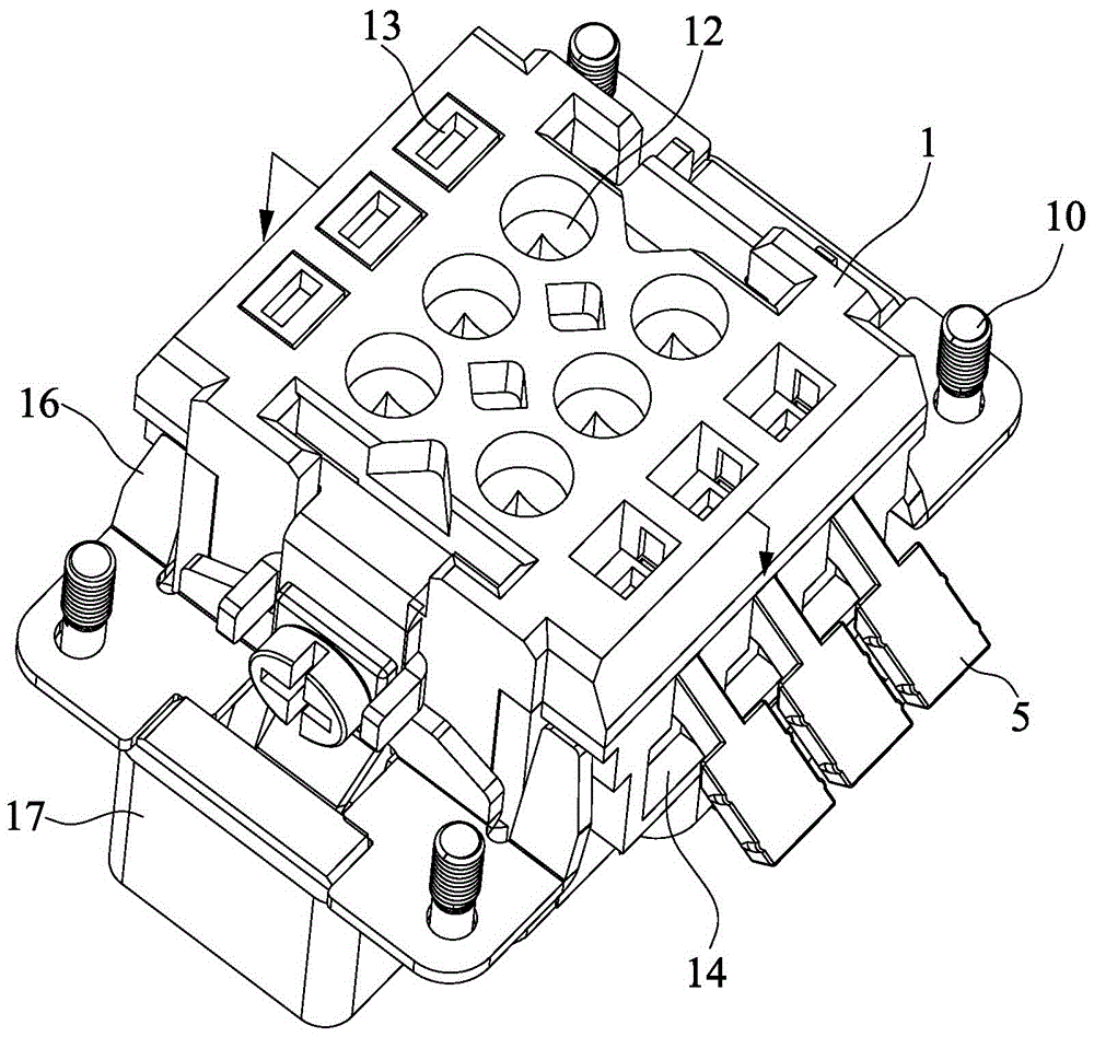
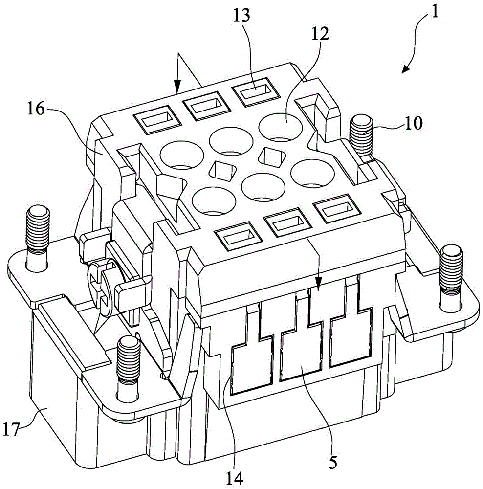
[0050] Such as Figure 1 to Figure 8 Shown is a preferred embodiment of the present invention, which discloses a connector that relies on strip-shaped hard metal torsion and pressure wiring.

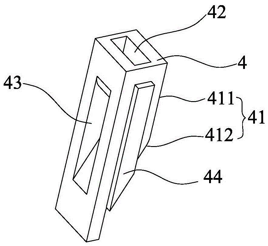
[0051] A lower insertion hole 11 is formed below the middle of the base body 1 for the insertion of the terminal 2, an upper insertion hole 12 is formed corresponding to the lower insertion hole 11 above the middle of the base body 1 for the insertion of the conductor 3, and an upper side insertion hole 13 is formed above the side of the base body 1 For the insertion of the push rod 4, a side groove 14 passing through the upper insertion hole 13 is formed on the side of the base body 1 for the installation of the push rod 5, and the upper insertion hole 12 and the lower insertion hole are formed between the upper insertion hole 12 and the lower insertion hole 11. 11 and the wiring cavity 15 of the jack 13 on the upper side. For the convenience of forming and assembling, the substrate 1 ...


PUM


Abstract

The invention discloses a connector for wire connection by virtue of twisting pressure of strip shaped hard metal. A lower jack is formed below the middle of a base, an upper jack is formed above the middle of the base, and an upper side jack is formed above the side of the base, a side groove perforating the upper side jack is formed on the side surface, a wire connection cavity perforating the upper jack, the lower jack and the upper side jack is formed between the upper jack and the lower jack; a terminal is inserted into the lower jack, a wire connection plate of the terminal is inserted and fixed in the wire connection cavity and connected with the terminal; the strip shaped hard metal twists into a Greece letter 'Sigma' shape and is mounted in the wire connection cavity, the vertical end is connected with the wire connection plate, and a splicing hole is formed on the transverse end and sleeved on the wire connection plate; a push rod is inserted into the upper side jack in a vertically sliding way, and a pushing surface for extruding the strip shaped hard metal is formed on the inner side of the push rod corresponding to the wire connection cavity; a deflector rod is pivoted on the side groove, and a pushing deflecting structure capable of pushing the push rod upwards or the deflector to swing outwards is formed between the inner side of the deflector rod and the outer side of the push rod. A conductor is conveniently assembled and disassembled by the connector, and prevented from being contacted and furthermore electric shock is avoided.

Description

technical field [0001] The invention relates to the technical field of connectors, in particular to a connector connected by twisting and pressing strip-shaped hard metal. Background technique [0002] In the prior art, there are many types of connectors, and the structures of various connectors are different, and there are also many wiring methods. After carefully analyzing the existing connectors, it is not difficult to find that there are roughly the following defects: [0003] 1. When some connectors are connected and disassembled with conductors, they must be completed with special tools, which is very inconvenient to operate; [0004] 2. During the connection and disassembly, the tools are easy to contact with the conductor, causing electric shocks from time to time, and the safety is poor; [0005] 3. During the wiring process, the tool cannot be removed and interferes with the conductor connection operation. [0006] In view of this, the inventor conducted in-dept...

Claims


Application Information

Patent Timeline
Patent Type & Authority Patents(China)
IPC IPC(8): H01R4/48H01R13/46
Inventor 罗奕奕
Owner XIAMEN WAIN ELECTRICAL
Why Eureka
Try Eureka