Housing, fastening member thereof, and display device incorporating housing

A technology for a housing structure and a display device, which is applied to the installation of support structures, connecting components, and identification devices, etc., can solve the problems of easy labor-consuming, inconvenient assembly operation, and damage to the surface of the circuit board with locking force, so as to reduce labor hours. , The effect of improving assembly efficiency

Active Publication Date: 2013-10-23
WISTRON CORP
View PDF2 Cites 2 Cited by
  • Summary
  • Abstract
  • Description
  • Claims
  • Application Information

AI Technical Summary

Problems solved by technology

[0002] Currently, in display devices such as LCD monitors or LCD TVs, a circuit board is usually installed between the casing and the backplane of the display screen. The common assembly method is to directly lock the circuit board to the casing or the backplane by screws. However, in the process of screw-locking the circuit board, it is easy to damage the surface of the circuit board due to excessive locking force
Furthermore, since the casing or the backplane does not have a structural design for positioning the circuit board, the assembler can only manually and visually align the perforations of the circuit board with the screw holes in the casing or the backplane, and then carry out the operation of screw locking , so the assembly operation is inconvenient and time-consuming

Method used


Image

  • Housing, fastening member thereof, and display device incorporating housing
  • Housing, fastening member thereof, and display device incorporating housing
  • Housing, fastening member thereof, and display device incorporating housing

Examples


Embodiment Construction

[0090] The foregoing and other technical contents, features and effects of the present invention will be clearly presented in the following detailed description of an embodiment with reference to the accompanying drawings. Through the description of the specific implementation, the technical means and effects of the present invention to achieve the intended purpose can be understood more deeply and specifically. However, the attached drawings are only for reference and description, and are not used to limit the present invention. .

[0091] Before the present invention is described in detail, it should be noted that in the following description, similar elements are denoted by the same reference numerals.

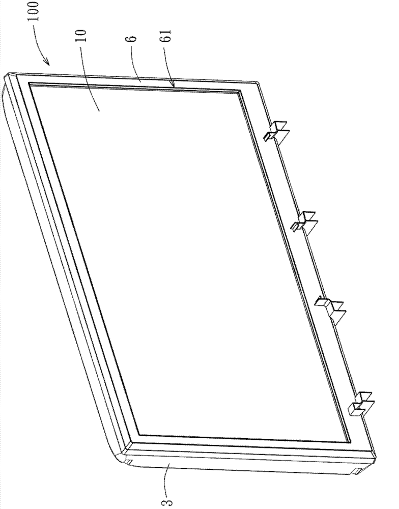
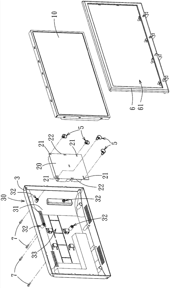
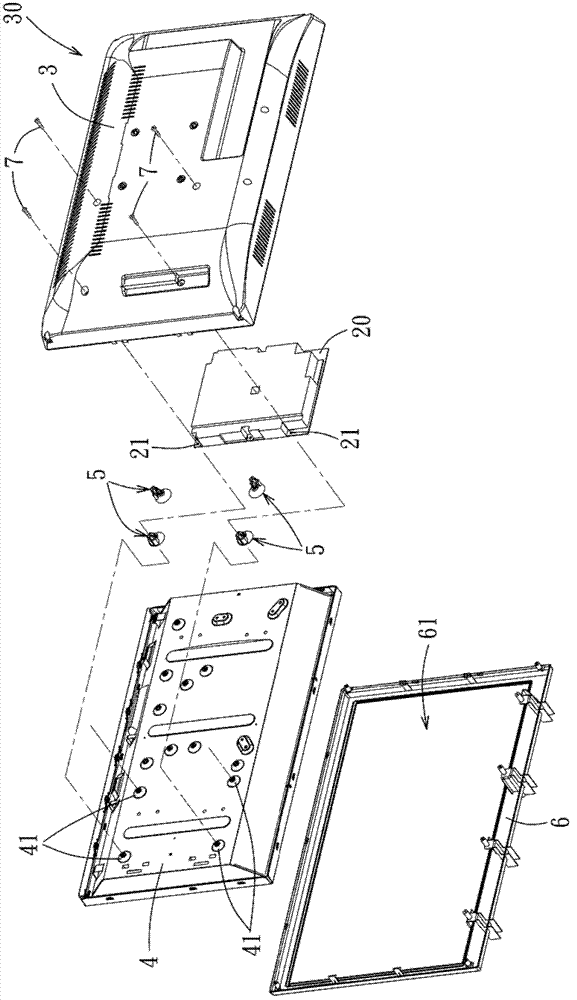
[0092] Such as figure 1 and figure 2 As shown, it is an embodiment of a display device with a housing structure in the present invention. The display device 100 can be a liquid crystal display or a liquid crystal television. The display device 100 includes a display modu...


PUM


Abstract

The invention discloses a housing, a fastening member thereof, and a display device incorporating the housing. The housing is suitable for securing a board member that is formed with an engaging hole. The housing includes an outer housing, a back plate and a fastening member. The outer housing includes an inner surface and a protruding post that protrudes from the inner surface. The back plate is disposed in the outer housing, is spaced apart from the inner surface, and includes a protrusion. The fastening member is disposed between the outer housing and the back plate, and includes a positioning cap, a positioning post, and an engaging hook. The positioning cap covers on the protrusion. The positioning post protrudes from the outer surface of the positioning cap and is engaged with the protruding post. The engaging hook includes a clamping plate that protrudes from the positioning post and that is spaced from the above of the positioning cap, and an engaging block that protrudes from the clamping plate towards the side of the positioning cap. The clamping plate and the positioning cap cooperatively clamp the board member therebetween. The engaging block is removably engaged in the engaging hole.

Description

technical field [0001] The invention relates to a housing structure, in particular to a housing structure for fixing a panel, its fixing parts and a display device with the housing structure. Background technique [0002] Currently, in display devices such as LCD monitors or LCD TVs, a circuit board is usually installed between the casing and the backplane of the display screen. The common assembly method is to directly lock the circuit board to the casing or the backplane by screws. However, in the process of screw-locking the circuit board, the surface of the circuit board is easily damaged due to excessive locking force. Furthermore, since the casing or the backplane does not have a structural design for positioning the circuit board, the assembler can only manually and visually align the perforations of the circuit board with the screw holes in the casing or the backplane, and then carry out the operation of screw locking , so the assembly operation is inconvenient and ...

Claims


Application Information

Patent Timeline
Patent Type & Authority Applications(China)
IPC IPC(8): H05K5/00H05K7/14G09F9/00F16B5/00
CPCF16B5/00H05K5/02G02F1/1333G09F9/00H05K7/14H05K5/00
Inventor 柯敏祥
Owner WISTRON CORP
Why Eureka
Try Eureka