A locking device and electronic equipment

A technology of locking device and electronic equipment, applied in the field of electronics, can solve the problems of cumbersome installation process, operation errors, etc., and achieve the effect of ensuring electrical connection performance, quality assurance, and low requirements for installation and operation specifications.

Active Publication Date: 2016-08-31
HUAWEI TECH CO LTD
View PDF4 Cites 0 Cited by
  • Summary
  • Abstract
  • Description
  • Claims
  • Application Information

AI Technical Summary

Problems solved by technology

[0006] In order to solve the problems of cumbersome installation process and prone to human error in the prior art, the embodiment of the present invention provides a locking device and electronic equipment

Method used


Image

  • A locking device and electronic equipment
  • A locking device and electronic equipment

Examples


Embodiment 1

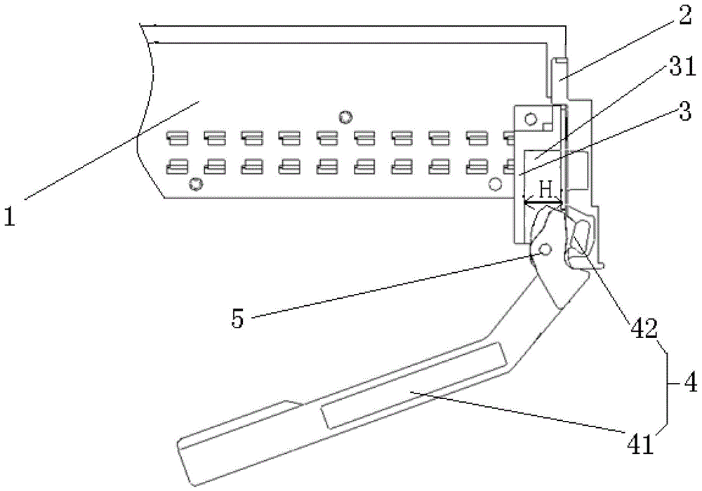
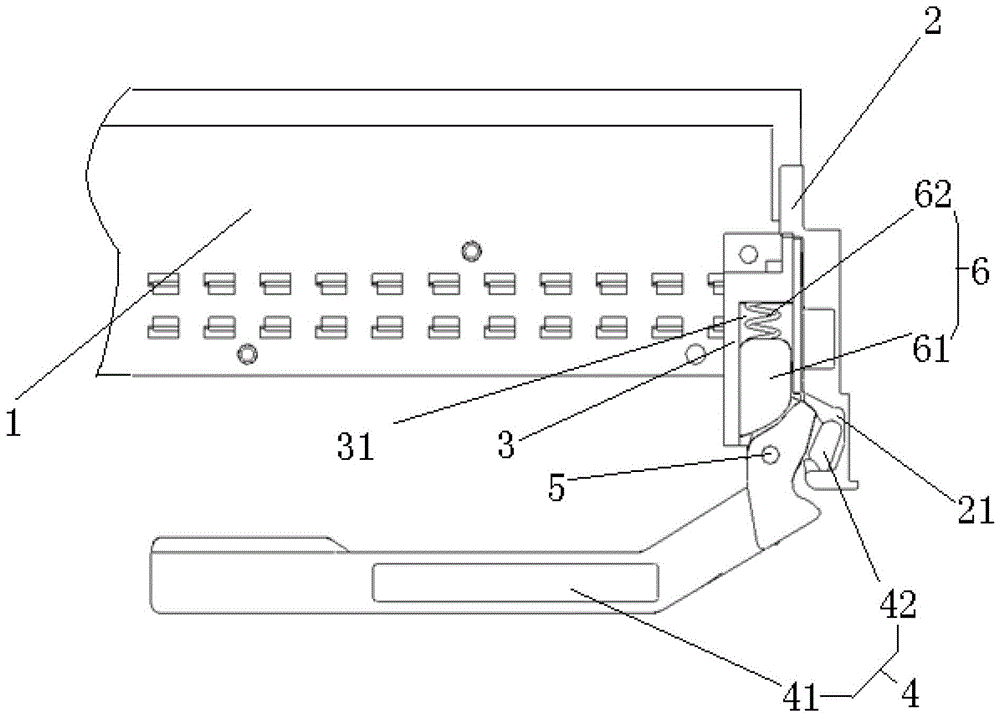
[0031] Such as figure 1 As shown, the embodiment of the present invention provides a locking device, the locking device includes: a bracket 3 and a locking structure 4, the bracket 3 is fixedly connected to the module 1, and the locking structure 4 is axially connected On the bracket 3, when working, the bracket 3 is located between the inner wall 2 of the electronic device and the module 1, and the locking structure 4 is in contact with the inner wall 2 of the electronic device, and by rotating The locking structure 4 increases the interaction force between the locking structure 4 and the inner wall 2 of the electronic device and locks each other.

[0032] Wherein, by rotating the locking structure 4, the interaction force between the locking structure 4 and the inner wall 2 of the electronic device is increased. Changes in the position of the contact of the inner walls 2 of the device result in different displacements and thus a change in the interaction force, causing them...

Embodiment 2

[0043] An embodiment of the present invention provides an electronic device, and a locking device is installed on the electronic device.

[0044] Wherein, the locking device in the embodiment of the present invention has the same structure and function as the locking device in the above embodiments, so it will not be repeated here. The embodiment of the present invention can make the locking structure and The interaction force of the inner wall of the electronic device can be increased and clamped to each other, and the locking structure is installed on the bracket, and the bracket is fixed to the module, so that the inner wall of the electronic device and the module are locked to each other, and the module is stable relative to the electronic device. Installation and positioning, this operation method is simple, fast and practical, has low requirements on the standardization of the operator's installation and operation, and is not prone to human error, so that the electrical c...


PUM


Abstract

The invention discloses a locking device and electronic equipment. The locking device comprises a support and a locking structure. The support is fixedly connected with a module. The locking structure is connected onto the support through a shaft. During working, the support is between the inner wall of the electronic equipment and the module and the locking structure is in contact with the inner wall of the electronic equipment. By turning the locking structure, the mutual acting force between the locking structure and the inner wall of the electronic equipment is increased and the locking structure and the inner wall of the electronic equipment are mutually and tightly clamped; and since the locking structure is installed on the support and the support is fixedly connected with the module, the inner wall of the electronic equipment is enabled to be mutually and tightly clamped with the module and the goal of stably installing and positioning the module relative to the electronic equipment is realized. The operating method is simple, the operation is rapid to conduct, the locking device is practical, the regulatory requirements on installation and operation of operators are lower, human-caused operating errors are not apt to occur, the performance of electric connection between the module and the electronic equipment is guaranteed and the quality of the produced electronic equipment is guaranteed.

Description

technical field [0001] The invention relates to the field of electronics, in particular to a locking device and electronic equipment. Background technique [0002] During the installation and maintenance of the electronic equipment, it is necessary to insert the module into the electronic equipment and connect it with the interfitting connector, and then it is necessary to continue to install and maintain other modules. The installed module is easily subjected to the force of other modules, which may change the installation position of the module in the electronic device, resulting in reduced performance or even failure of the electrical connection between the module and the electronic device. [0003] At present, high-speed signals impose strict requirements on the mating dimensional accuracy of the intermatable connector. In order to control the mating dimensional accuracy of the intermatable connector, the module is required to be positioned with the intermatable connecto...

Claims


Application Information

Patent Timeline
Patent Type & Authority Patents(China)
IPC IPC(8): H05K7/12
Inventor 刘雄彪白磊彭乐雄
Owner HUAWEI TECH CO LTD
Why Eureka
Try Eureka