Waveguide-type optical switch

一种光开关、波导的技术,应用在波导型光开关领域,能够解决信号处理成为瓶颈等问题

Active Publication Date: 2013-10-23
NIPPON TELEGRAPH & TELEPHONE CORP
View PDF3 Cites 9 Cited by
  • Summary
  • Abstract
  • Description
  • Claims
  • Application Information

AI Technical Summary

Problems solved by technology

[0003] However, in a communication network, in a node where a plurality of transmission paths are gathered, it is necessary to route or switch signal paths, and these signal processing is increasingly becoming a bottleneck as transmission capacity increases

Method used


Image

  • Waveguide-type optical switch
  • Waveguide-type optical switch
  • Waveguide-type optical switch

Examples


no. 1 approach )

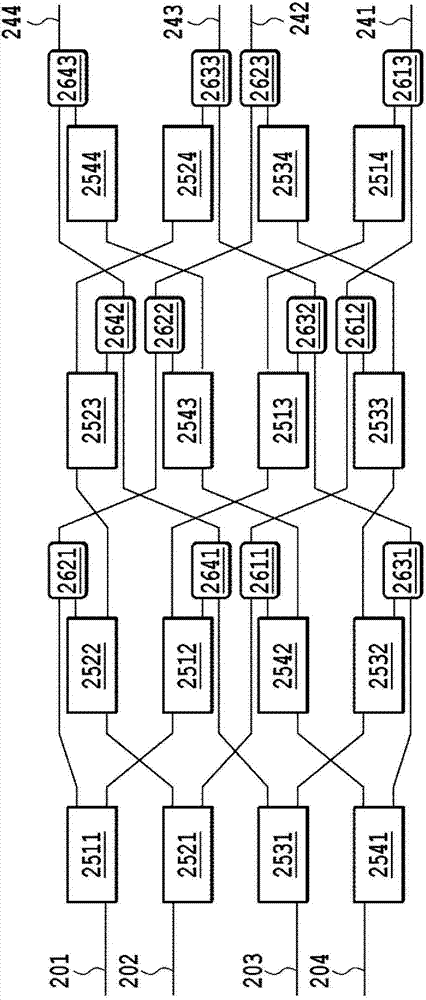
[0039] figure 2 is a schematic diagram showing the first embodiment of the present invention, and figure 2 A configuration example of a matrix optical switch with four inputs and four outputs is shown.

[0040] figure 2 The matrix optical switch shown is composed of 16 unit optical switching elements with single input and double output (2511-2514, 2521-2524, 2531-2534, 2541-2544) and 12 unit optical confluence elements with double input and single output ( 2611-2613, 2621-2623, 2531-2633, 2641-2643). Four unit optical switch elements 2511 , 2512 , 2513 , and 2514 are connected in a column to form a single-input and four-output optical switch 211 (symbols not shown in the figure). Similarly, the unit optical switch elements 2521-2524, 2531-2534, and 2541-2544 are respectively connected in columns to form optical switches 212, 213, and 214 with one input and four outputs (symbols not shown in the figure).

[0041] The three unit photocombining elements 2611 , 2612 , and 2...

no. 2 approach )

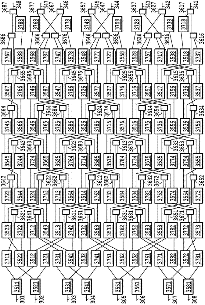
[0053] image 3 is a schematic view showing the second embodiment of the present invention, in which an example of a matrix optical switch constituting eight inputs and eight outputs is shown.

[0054] image 3The matrix optical switch shown is composed of 64 single-input and double-output unit optical switch elements (3511-3518, 3521-3528, 3531-3538, 3541-3548, 3551-3558, 3561-3568, 3571-3578, 3581-3588 ), 64 single-input and single-output photograting switch elements (3711-3718, 3721-3728, 3731-3738, 3741-3748, 3751-3758, 3761-3768, 3771-3778, 3781-3788) and 56 dual Input and single output unit photosynthetic components (3611-3617, 3621-3627, 3631-3637, 3641-3647, 3651-3657, 3661-3667, 3671-3677, 3681-3687). Eight unit optical switch elements 3511, 3512, 3513, 3514, 3515, 3516, 3517, 3518 are connected in columns, and the output port of each unit optical switch is connected with a grating optical switch element 3711- 3718 to form a single-input and eight-output optical sw...

no. 3 approach )

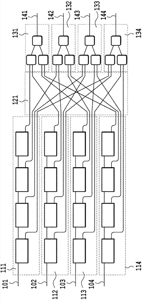
[0069] In the above-mentioned first embodiment and second embodiment, for M=N=4 and M=N=8 (that is, the case of M=N), the waveguide in the form of a matrix optical switch with M input and N output type optical switches are described. However, as long as M and N are different and are an integer of 3 or more, the arrangement of the present invention can be implemented. That is, the waveguide type optical switch of the present invention can be implemented as long as it has at least the following features.

[0070] [1] The waveguide optical switch is a matrix optical switch composed of M single-input and N-output optical switches and N M-input and single-output optical combiners. The a-th (a is an integer greater than 1 and less than M) input of the matrix optical switch is composed of the input of the a-th single-input and N-output optical switch. The bth (b is an integer greater than 1 and less than N) output of the matrix switch is composed of the output of the bth M-input si...


PUM

PropertyMeasurementUnit
sizeaaaaaaaaaa
wavelengthaaaaaaaaaa
refractive indexaaaaaaaaaa

Abstract

Provided is a waveguide-type optical switch, which is a matrix optical switch having a many-to-one and one-to-many connection function, constituted by connecting a single optical switch element and an optical coupler or an optical splitter. Therein, the number of crossings is reduced, and the switch can be fabricated on a single substrate. According to one embodiment of the present invention, an M-input 1-output optical coupler is divided up into (M-1) 2-input, 1 output single optical coupler elements, and of the N output ports of the 1-input N-output optical switch, is positioned immediately after the (N-1)th output port, excluding the output port nearest to the input of the matrix optical switch. Therefore, the output port of each optical switch crosses after being merged at the single optical coupler element, rather than merging at the optical coupler after crossing, which reduces the number of crossings in the matrix optical switch as a whole.

Description

technical field [0001] The present invention relates to a waveguide type optical switch used in applications such as optical communication, in particular, to a matrix optical switch configured to connect an optical switch with an optical combiner or an optical splitter, the matrix optical switch has many-to-one or one-to-one Many connection functions. Furthermore, the present invention also relates to a technique for realizing a loop configuration with a reduced number of waveguide crossings. Background technique [0002] The optical communication technology using optical fiber as the transmission medium increases the transmission distance of the signal, thus forming a large-scale optical communication network. In recent years, with the wide spread of Internet communication, the communication volume has increased rapidly, and the demand for large capacity, high speed, and high functionality of the communication network has gradually increased. Hitherto, by introducing a mu...

Claims


Application Information

Patent Timeline
Patent Type & Authority Applications(China)
IPC IPC(8): G02F1/313G02B6/12
CPCH04Q2011/0052G02F1/0147G02B6/3594G02B2006/12145G02F1/3137G02B6/3546G02F1/225H04Q11/0005G02F2001/212G02F1/212
Inventor 渡边俊夫铃木贤哉乡隆司山崎裕史森淳
Owner NIPPON TELEGRAPH & TELEPHONE CORP
Why Eureka
Try Eureka