
Magnetic locking device

A locking device and magnetic technology, applied in the direction of building fasteners, wing fan fasteners, buildings, etc., can solve the problems of short use time, weak locking, loud noise, etc., and achieve long service life and simple structure. , noise-free effect

Inactive Publication Date: 2013-10-30
孙莹
View PDF0 Cites 3 Cited by
  • Summary
  • Abstract
  • Description
  • Claims
  • Application Information

AI Technical Summary

Problems solved by technology

The current locking device is generally a snap-in lock, and the use time is short, it is easy to be locked in a loose situation, and it is easy to be brittle due to adsorption and collision, and there is a lot of noise when it is fixed.

Method used


Image

  • Magnetic locking device

Examples


Embodiment Construction

[0010] Below in conjunction with accompanying drawing, the present invention is described in further detail:

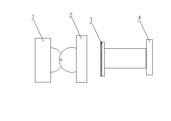
[0011] The magnetic locking device includes a magnetic support 1, a magnetic disc 2, a rubber pad 3, and a support 4 for a suction plate. When installing, first find the installation location, and then directly adsorb the magnetic support 1 on the iron door or the rotating facility (if it is not iron, use screws to fix it), similarly install the suction plate support 4 to the corresponding position and fix it . After opening the door, the magnetic sucker 2 on the door and the support of the rubber pad 3 are close to each other, and they are sucked, so that the door can be fixed.


PUM


Abstract

The invention relates to a locking device, and in particular relates to a magnetic locking device for realizing random rotation of a fixed rotating door or other freely rotated facilities. The magnetic locking device comprises a magnetic suction support seat, a magnetic suction cup, a rubber mat and a suction plate support seat. Compared with buckling type locking, the magnetic locking device not only has reliable locking function, but also has the advantages of being simple in structure, free from noise and long in service life.

Description

technical field [0001] The present invention designs a locking device, in particular a magnetic locking device for fixing a revolving door or other facilities to rotate freely. Background technique [0002] For the convenience of revolving doors or other revolving facilities being blown closed by wind, people often install locking devices under the feet of revolving facilities to fix doors or other revolving facilities. The current locking device is generally a snap-in lock, which is short in use, prone to loose locking, brittle fracture due to adsorption and collision, and relatively loud noise when fixed. Contents of the invention [0003] The object of the present invention is to remedy the above-mentioned shortcomings and provide a magnetic locking device. It can fix doors or other rotating facilities, which is convenient and labor-saving, has a long service life and low noise. [0004] The technical scheme of the present invention is: the magnetic locking device inc...

Claims


Application Information

Patent Timeline
IPC IPC(8): E05C17/56
Inventor 孙莹
Owner 孙莹
Learn More