Fluid control element

A technology for controlling components and fluids, which is applied to engine components, valve details, multi-way valves, etc., and can solve problems such as load breakage and high bearing capacity of sealing rings

Active Publication Date: 2013-10-30
BURKERT WERKE
View PDF8 Cites 7 Cited by
  • Summary
  • Abstract
  • Description
  • Claims
  • Application Information

AI Technical Summary

Problems solved by technology

In the area of ​​the passage of the shaft through the sealing ring, the sealing ring is subjected to high loads and can break at any time

Method used


Image

  • Fluid control element
  • Fluid control element
  • Fluid control element

Examples


Embodiment Construction

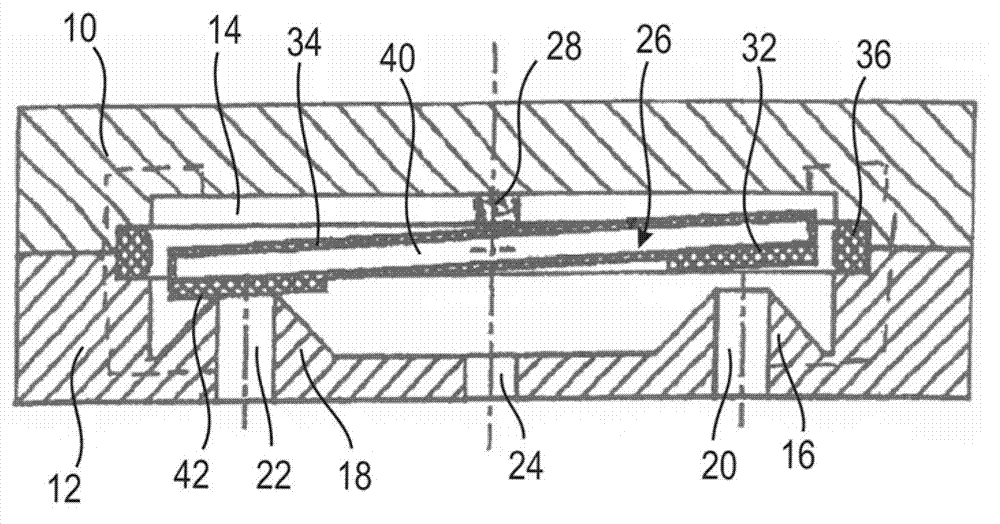
[0042] figure 1 Fluid control element showing 3 / 2-way function, which is part of a 3 / 2-way valve.

[0043] The control element comprises a preferably flat, cuboid housing consisting of two housing parts 10 , 12 pressed against each other.

[0044] Formed between the housing parts 10 , 12 is a fluid chamber 14 which is delimited by a recess in the housing parts 10 , 12 .

[0045] Two sealing seats 16 , 18 , also called valve seats, protrude into the fluid chamber 14 . The sealing seats 16 , 18 surround the inlets of the associated fluid channels 20 , 22 which start in the fluid chamber 14 or open into the fluid chamber. The fluid channels 20 , 22 pass through the housing part 10 and are connected to a piping system (not shown). This also applies to the fluid channel 24 which is formed without a valve seat and which preferably leads between the sealing seats 16 , 18 to the fluid chamber 14 or from the fluid chamber.

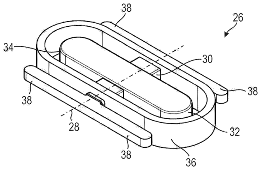
[0046] Located in the fluid chamber 14 is a valve body 26...


PUM


Abstract

A fluidic control element comprises a housing composed of at least two housing parts, a fluid space being formed between the housing parts and at least first and second flow channels each comprising a sealing seat opening into said fluid space, and a valve body defined by a two-armed lever which can be swiveled in the fluid space and defines a combined sealing and actuating element, each arm of the lever being capable of closing and opening its associated flow channel in a corresponding end position. The valve body has a load-carrying core including a shaft mounted in the housing and an elastic sealing sheath surrounding the core in sections, the shaft being embedded in the sealing sheath at least in the region of its mounting in the housing. The sealing sheath comprises a formed-on sealing ring which is clamped between the housing parts and surrounds the lever arms. The shaft is rounded at least in the region in which it is embedded in the sealing ring and adjoins the sealing ring.

Description

technical field [0001] The invention relates to a fluid control element with a housing consisting of at least two housing parts, wherein a fluid chamber is formed between the housing parts, at least a first and a second fluid channel leading into the fluid chamber, said fluid channel Each has a sealing seat, and the fluid control element also has a valve body that can swing in the fluid chamber, and the valve body is in the form of a combined sealing and operating element designed as a double-arm lever, wherein each arm of the lever is in the corresponding The end positions of the valve body can close and open its associated fluid channel, wherein the valve body has a load-bearing core and an elastic sealing cover, the core has a shaft, which engages in the seal at least in its bearing area in the housing In the housing, wherein the sealing housing has a shaped sealing ring, which is clamped between the housing parts and surrounds the lever arm. Background technique [0002...

Claims


Application Information

Patent Timeline
Patent Type & Authority Applications(China)
IPC IPC(8): F16K11/16F16K31/06
CPCF16K37/0033F16K11/0525F16K31/0624
Inventor 拉尔夫·沙伊贝
Owner BURKERT WERKE
Why Eureka
Try Eureka