Double-layer cylindrical permanent magnetic coupler

A permanent magnetic coupling, barrel-type technology, applied in the direction of permanent magnetic clutch/brake, electric brake/clutch, electrical components, etc., can solve the problems of vibration isolation, energy saving, power waste, etc., and achieve simple installation and debugging , increase the coupling area and avoid the effect of axial thrust

Inactive Publication Date: 2018-05-18
盐城市金海洋机电科技有限公司
View PDF0 Cites 2 Cited by
  • Summary
  • Abstract
  • Description
  • Claims
  • Application Information

AI Technical Summary

Problems solved by technology

[0002] The existing motor systems basically have the phenomenon of large horses and small carts, and the waste of electric energy is serious, and the traditional mechanical coupling inevitably transmits vibration from one end to the other through the coupling, which obviously does not have the ability to isolate vibration and Energy-saving performance, using energy-saving technologies such as permanent magnet eddy current flexible transmission to optimize system operation and control, and improve the overall operating efficiency of the system

Method used


Image

  • Double-layer cylindrical permanent magnetic coupler

Examples


Embodiment Construction

[0012] The present invention will be described in further detail below in conjunction with the accompanying drawings and embodiments.

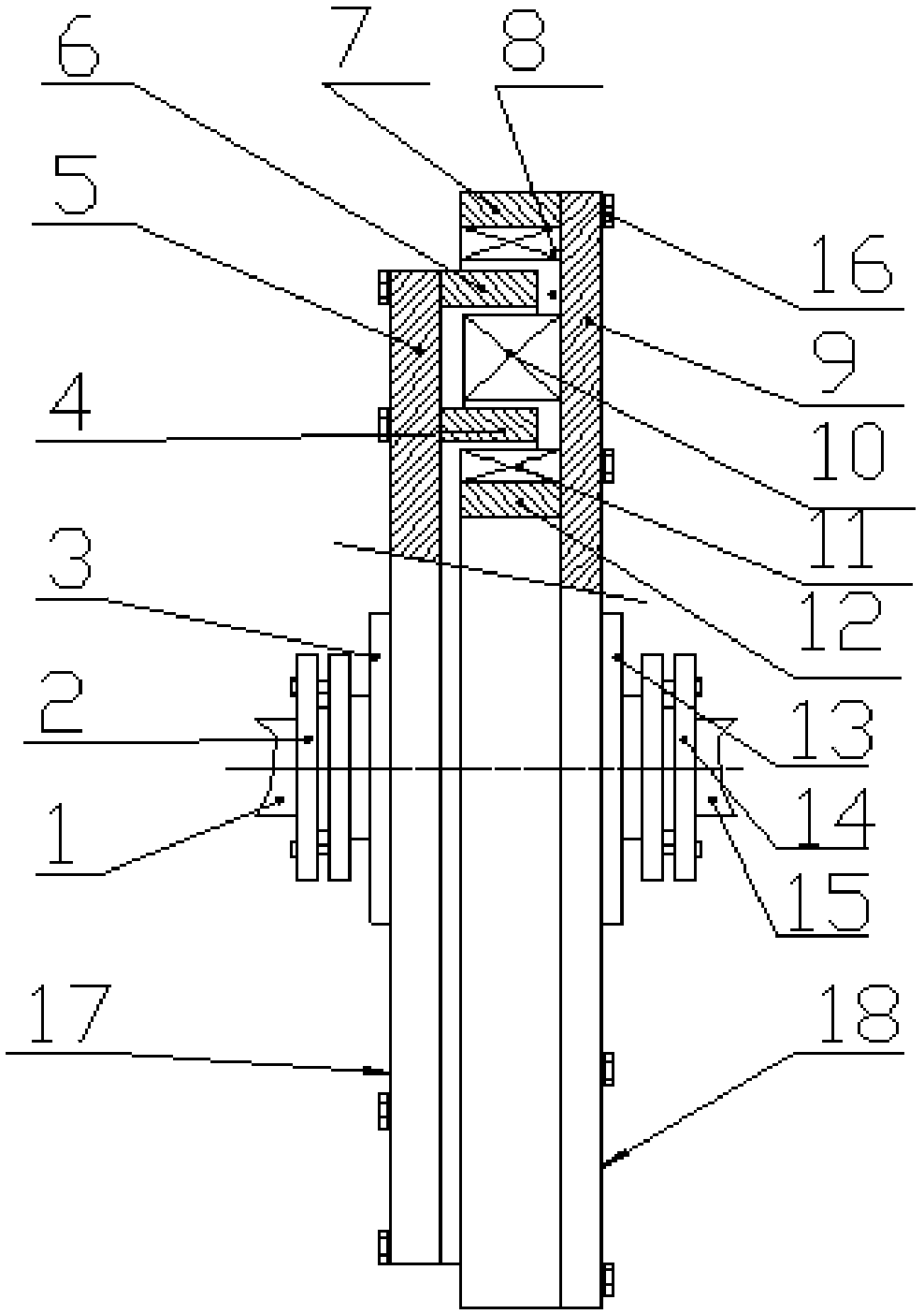
[0013] Such as figure 1 As shown, the double-layer cylindrical permanent magnetic coupler of the present invention includes a split and coaxial first rotor (17) and a second rotor (18), the first rotor (17) is a cylindrical permanent magnetic rotor, and its It consists of an outer magnetic ring, a middle magnetic ring and an inner magnetic ring installed on a non-ferromagnetic permanent disk (9). There is an annular gap between the outer magnetic ring and the middle magnetic ring, and there is a ring gap between the middle magnetic ring and the inner magnetic ring. In the gap, the outer magnetic ring is composed of a ferromagnetic outer cylinder (7) and a permanent magnet one (8) fixed on the inner side of the outer cylinder, and the outer cylinder (7) is installed together with the permanent disk (9) by screws (16). The inner magnetic ring i...


PUM


Abstract

Provided is a double-layer cylindrical permanent magnetic coupler. The double-layer cylindrical permanent magnetic coupler is composed of a first rotor and a second rotor; the first rotor is a cylindrical permanent magnetic rotor and composed of an outer magnetic ring, a middle magnetic ring and an inner magnetic ring which are installed at a non-ferrousmagnetic permanent magnetic disc, an annulargap is formed between the outer magnetic ring and the middle magnetic ring, and an annular gap is formed between the middle magnetic ring and the inner magnetic ring; the outer magnetic ring is composed of a ferro-magnetic outer cylinder and a permanent magnet fixed to the inner side of the outer cylinder, the inner magnetic ring is composed of a ferro-magnetic inner cylinder and a permanent magnet fixed to the outer side of the inner cylinder, and the middle magnetic ring is composed of a permanent magnet installed on the non-ferrousmagnetic permanent magnetic disc; the second rotor is a conductor rotor composed of an outer conductor ring and an inner conductor ring which are installed on a non-ferrousmagnetic installation disc, wherein the outer conductor ring of the second rotor is located in the gap between the outer permanent magnetic ring and a middle permanent magnetic ring and forms a coupling relationship with the permanent magnets on the outer permanent magnetic ring and themiddle permanent magnetic ring through air gaps, and the inner conductor ring forms a coupling relationship with the permanent magnets on the middle permanent magnetic ring and the inner permanent magnetic ring through air gaps. The first rotor is connected to a first shaft, the second rotor is connected to a second shaft, and the first shaft and the second shaft can be an input shaft or an output shaft for each other. The magnetic pole directions of the permanent magnets installed on the outer permanent magnetic ring, the middle permanent magnetic ring and the inner permanent magnetic ring are perpendicular to the axis of a rotary disc, and magnetic poles of adjacent magnets are different.

Description

technical field [0001] The invention relates to a double-layer cylindrical permanent magnet shaft coupling, which belongs to the technical field of energy saving. Background technique [0002] The existing motor systems basically have the phenomenon of big horses and small carts, and the waste of electric energy is serious, and the traditional mechanical coupling inevitably transmits vibration from one end to the other through the coupling, which obviously does not have the ability to isolate vibration and Energy-saving performance, using energy-saving technologies such as permanent magnet eddy current flexible transmission to optimize system operation and control, and improve the overall operating efficiency of the system. [0003] In this case, the permanent magnet coupler is a new ideal choice in the field of motor energy saving. Contents of the invention [0004] The invention aims to provide a double-layer cylindrical rotating disk permanent magnetic coupler with lar...

Claims


Application Information

Patent Timeline
IPC IPC(8): H02K49/10
CPCH02K49/108
Inventor 朱广军
Owner 盐城市金海洋机电科技有限公司
Why Eureka
Try Eureka