Paper currency handling device and paper currency transaction device

A banknote processing device and technology for banknotes, applied in the direction of processing coins or valuable banknotes, instruments, etc., can solve the problems of lower overall efficiency of the device, difficulty in determining jammed banknotes, banknote jamming, etc., and achieve the effect of suppressing the reduction of overall efficiency.

Active Publication Date: 2013-10-30
HITACHI OMRON TERMINAL SOLUTIONS CORP
View PDF7 Cites 9 Cited by
  • Summary
  • Abstract
  • Description
  • Claims
  • Application Information

AI Technical Summary

Problems solved by technology

This reversing conveyance path requires complex operations to invert banknotes
Therefore, banknote jams (banknote jams) tend to occur more easily than other conveyance paths, and countermeasures against banknote jams are required.
However, in the conventional reversing conveyance path, in order to identify jammed banknotes, the identification result of the identification unit of the banknote must be used, and it is difficult to judge jammed banknotes on the reversed conveyance path.
In addition, the reversing conveyance path is generally a one-way conveyance path for one-way conveyance, and the banknotes must be stopped for removal, and the overall efficiency of the device is reduced.

Method used


Image

  • Paper currency handling device and paper currency transaction device
  • Paper currency handling device and paper currency transaction device
  • Paper currency handling device and paper currency transaction device

Examples


Embodiment 1

[0025] Hereinafter, a first embodiment of the present invention will be described using the drawings.

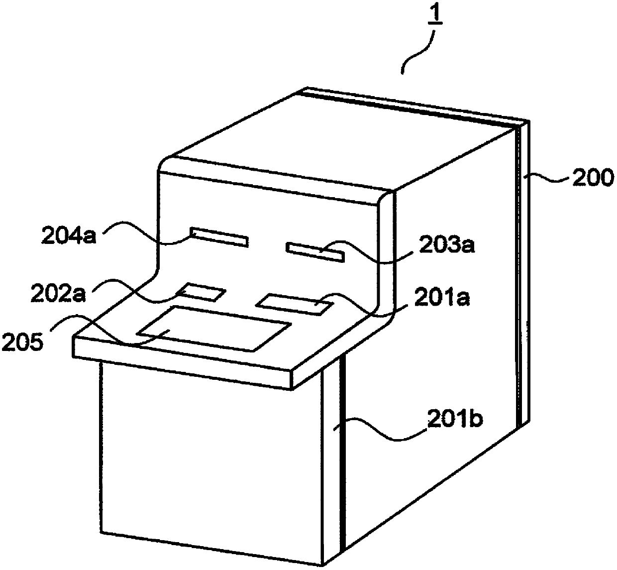
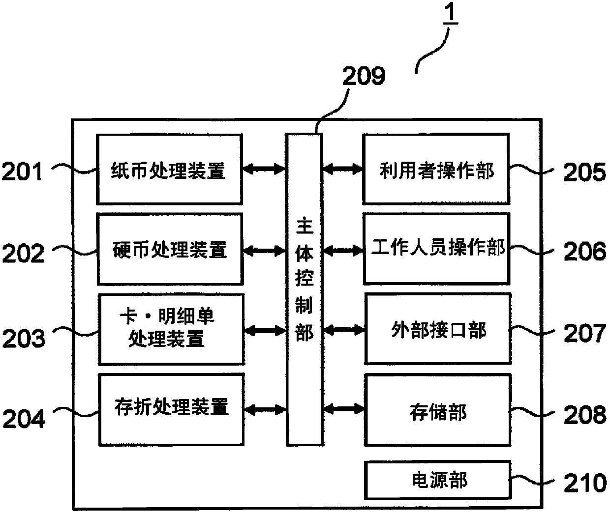
[0026] first use figure 1 , figure 2 The configuration of an automatic transaction device (hereinafter referred to as ATM) will be described. An ATM is a device that uses cash cards, banknotes, statement slips, and the like as transaction media, and performs processes such as cash deposit, payment, and transfer through user operations.

[0027] figure 1 It is a perspective view of the appearance of ATM1. The banknote processing apparatus (lower right side) which handles banknotes, and the coin processing apparatus (lower left side) which handles coins are installed in the lower part of ATM1. The housing of ATM1 is provided with the shutter 201a so that it may oppose the deposit and withdrawal port of a banknote processing apparatus, and the deposit and withdrawal transaction of a banknote is performed according to opening and closing of this shutter 201a. Similarly, on...

Embodiment 2

[0059] Hereinafter, a second embodiment of the present invention will be described using the drawings. In this embodiment, the case where the jammed banknote detected on the reversing conveyance path is removed is demonstrated. In addition, since the structure of ATM1, the structure of the front and back reversing means 107, etc. are the same as 1st Embodiment, description is abbreviate|omitted.

[0060] Figure 8 and Figure 9 It is a figure which shows the conveyance state of the jammed banknote X. Jammed banknote X( Figure 8 (a)), transported to the position of the distributing door 11 by the turning conveying path 108c ( Figure 8 (b)). At this time, it is preferable to release the connection state of the conveyance rollers 16, 17 and the conveyance rollers 13 to 15 when the conveyance path of the reversing conveyance path 108c is equal to or greater than a predetermined value so as to block the banknote X after colliding with the dispensing gate 11. are not conveye...

Embodiment 3

[0064] Hereinafter, a third embodiment of the present invention will be described using the drawings. In this embodiment, the case where the jammed banknote detected on the reversing conveyance path is removed by the operation|movement different from the said 2nd Embodiment is demonstrated. In addition, since the structure of ATM1, the structure of the front-back inversion unit 107, etc. are the same as those of 1st and 2nd embodiment, description is abbreviate|omitted.

[0065] Figure 10 and Figure 11 It is a figure which shows the conveyance state of the jammed banknote X. The jammed banknote X detected by the sensor is conveyed to the position ( Figure 10 ). At this time, it is preferable to change the connection state of the conveying rollers 16, 17 and the conveying rollers 13 to 15, and to change the speed of the conveying rollers 16, 17 so that the jammed banknote X does not bounce back after colliding with the end surface 19a of the turning space. .

[0066] A...


PUM


Abstract

The invention provides a paper currency handling device and a paper currency transaction device. The detection of the paper currency blocking on a turnover conveying path becomes easier and the removing of the blocked paper currency is easier. The paper currency handling device includes a paper currency slot unit for a user to take out and put in the paper currency; an identification unit identifying the front and back sides of the paper currency; a front and back side turnover unit arranged behind the identification unit and turning over the front and back sides of the paper currency; a temporary keeping unit connected with the rear part of the front and back side turnover unit and temporarily keeping the paper currency in transaction; and a conveying path for conveying the paper currency to the paper currency slot unit, the identification unit, and the front and back side turnover unit. The front and back side turnover unit is provided with a turnover conveying path capable of bidirectionally conveying the paper currency and turning over the front and back sides and a non-turnover conveying path capable of bidirectionally conveying the paper currency without turning over the front and back sides.

Description

technical field [0001] The present invention relates to a banknote handling device and an automatic transaction device used by, for example, financial institutions equipped with the banknote handling device. Background technique [0002] Some automatic transaction devices (hereinafter referred to as ATM (Automated Teller Machine)) used by financial institutions such as banks are provided with a mechanism for reversing the front and back of banknotes. The front-back reversing mechanism is a mechanism for reversing the face of the banknote deposited by the user. By using the front-back reversing mechanism, when a banknote is stored in the storage, the orientation of the front or back of the banknote can be aligned, and payment can be made with the orientation of the front or back of the banknote aligned. Depositing and withdrawing money with the front and back faces of the banknotes in the same state improves convenience for users of ATMs and employees of financial institutio...

Claims


Application Information

Patent Timeline
Patent Type & Authority Applications(China)
IPC IPC(8): G07D13/00
Inventor 野村丹香寺尾祐宣腰塚久洋
Owner HITACHI OMRON TERMINAL SOLUTIONS CORP
Why Eureka
Try Eureka