Coaxial wide-band filter

A filter and broadband technology, applied in the field of microwave communication equipment, can solve problems such as large circuit size

Inactive Publication Date: 2013-10-30
NANJING SAIGEW MICROWAVE SCI & TECH
View PDF2 Cites 8 Cited by
  • Summary
  • Abstract
  • Description
  • Claims
  • Application Information

AI Technical Summary

Problems solved by technology

The stub filter scheme can also achieve wid

Method used


Image

  • Coaxial wide-band filter
  • Coaxial wide-band filter
  • Coaxial wide-band filter

Examples


Embodiment Construction

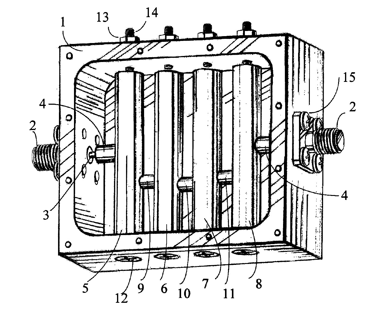
[0013] refer to figure 1 . The broadband filter of the present invention is implemented in a rectangular cavity 1 . The input and output radio frequency connectors 2 are installed on the left and right metal walls of the cavity 1 through screws 12 . The resonant rods 5, 6, 7, 8 are installed on the lower metal wall of the cavity 1 at equal intervals in sequence through the bottom screws 12 of the cavity, and there is a certain distance between the top of the cavity and the cavity. Tuning screws 14 are installed facing each resonance rod on the metal wall on the upper side of the cavity, and the locking is realized by nuts 13. The adjacent circular rod-shaped resonance rods from left to right are respectively connected with short metal rods 9, 10, 11. The resonant rod 5 at the input end and the resonant rod 8 at the output end are equipped with thick rod taps 4 respectively, and are connected with the inner conductor 3 of the radio frequency connector.

[0014] The above co...


PUM


Abstract

A coaxial wide-band filter is arranged in a rectangular metal cavity, and comprises an input radio frequency connector, an output radio frequency connector, a plurality of open-ended quarter-wave coaxial resonators arranged on a metal wall at the lower side, coupling short rods, thick rod taps, tuning screws and a cavity covering plate, which the input radio frequency connector and the output radio frequency connector are arranged on a left metal wall and a right metal wall of the cavity, each coupling short rod is arranged between any two adjacent coaxial resonators, the thick rod taps connect conductors inside the radio frequency connectors, an input end resonator and an output end resonator, and the tuning screws are respectively arranged above the opened ends of the coaxial resonators. Due to the adoption of the short rods for coupling, the coupling strength between every two adjacent resonators is largely improved, and a wider transmission band can be achieved. Cross coupling exists between the separated resonators, the filter has asymmetric frequency response, and the suppression degree outside a higher end of the transmission band is high.

Description

technical field [0001] The invention belongs to the technical field of microwave communication equipment, and in particular relates to the design of a microwave coaxial cavity broadband filter. Background technique [0002] The design of microwave filters is one of the key issues in the design of civil and military communication systems. The use of filters can separate signals in different frequency ranges and reduce mutual interference. It is generally considered that a band-pass filter with a fractional bandwidth of more than 20% is a wide-band filter. Commonly used microwave bandpass filter schemes, such as comb line bandpass filter scheme and parallel coupling bandpass filter scheme, encounter difficulties in realizing broadband filters. The main problem is that it is difficult to achieve strong inter-resonator coupling and input output coupling. The interdigital filter can achieve a wide bandwidth, but the distance between the resonators is often small, and the proces...

Claims


Application Information

Patent Timeline
IPC IPC(8): H01P1/207
Inventor 于立刘云
Owner NANJING SAIGEW MICROWAVE SCI & TECH
Why Eureka
Try Eureka