Supercharge Your Innovation With Domain-Expert AI Agents!

Remote-control type antenna

A remote control antenna technology, applied in the direction of the antenna support/installation device, etc., can solve the problems of shaking, restriction, and low positioning accuracy of the remote control antenna, and achieve the effect of stable antenna position and high position adjustment accuracy

Inactive Publication Date: 2013-10-30
DUJIANGYAN AISITE TECH
View PDF0 Cites 0 Cited by
  • Summary
  • Abstract
  • Description
  • Claims
  • Application Information

AI Technical Summary

Problems solved by technology

[0002] The remote-controlled antenna is favored by the majority of users because of its ease of use, but the remote-controlled antenna in the prior art is greatly limited in the field of high-speed communication due to its low positioning accuracy and being easily affected by strong winds and shaking.

Method used


Image

  • Remote-control type antenna
  • Remote-control type antenna
  • Remote-control type antenna

Examples


Embodiment Construction

[0017] The preferred embodiments of the present invention will be described in detail below in conjunction with the accompanying drawings, so that the advantages and features of the present invention can be more easily understood by those skilled in the art, so as to define the protection scope of the present invention more clearly.

[0018] The invention provides a remote-controlled antenna with slide rails and screw rods, high position adjustment accuracy and relatively stable antenna position, suitable for the field of high-speed communication.

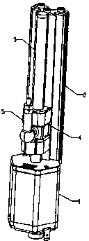
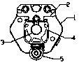
[0019] Such as figure 1 , figure 2 As shown, a remote control antenna includes a motor 1 and a launch rod 5, and the antenna also includes a screw 3 and a slider 4, the screw 3 is connected with the rotating shaft of the motor 1, and the slider 4 is connected to the The screw rod 3 is threaded, and the launching rod 5 is threaded with the slide block 4 .

[0020] Such as figure 1 , figure 2 As shown, the antenna further inclu...


PUM


Abstract

The invention discloses a remote-control type antenna which comprises a motor and a transmitting rod. The remote-control type antenna further comprises a threaded rod and a sliding block, wherein the threaded rod is connected with a rotation shaft of the motor, the sliding block is connected with the threaded rod in a threaded mode, and the transmitting rod is connected with the sliding block in a threaded mode. The remote-control type antenna has the advantages of being provided with a sliding rail and the threaded rod and being high in position adjustment accuracy, stable in antenna position and suitable for the field of high-speed communication.

Description

technical field [0001] The invention relates to an antenna, more precisely a remote control antenna. Background technique [0002] The remote-controlled antenna is favored by the majority of users because of its ease of use, but the remote-controlled antenna in the prior art is greatly limited in the field of high-speed communication due to its low positioning accuracy and being easily affected by strong winds and shaking. . Contents of the invention [0003] The present invention mainly solves the technical problems existing in the prior art, thereby providing a remote-controlled antenna with slide rails and screw rods, high position adjustment precision, relatively stable antenna position, and suitable for high-speed communication field. [0004] Above-mentioned technical problem of the present invention is mainly solved by following technical scheme: [0005] A remote control antenna, including a motor and a transmitting rod, the antenna also includes a screw and a sl...

Claims


Application Information

Patent Timeline
IPC IPC(8): H01Q1/22
Inventor 龚镇
Owner DUJIANGYAN AISITE TECH
Features
  • R&D
  • Intellectual Property
  • Life Sciences
  • Materials
  • Tech Scout
  • Unparalleled Data Quality
  • Higher Quality Content
  • 60% Fewer Hallucinations
Learn More