
A rubber sheet cutting structure

A technology of rubber sheets and backing sheets, applied in metal processing, etc., can solve the problems of complex multi-hole simultaneous cutting equipment, low production efficiency of manual cutting, expensive equipment, etc., and achieve the effect of simple structure, high production efficiency and convenient operation

Active Publication Date: 2020-04-17
广东邦达实业有限公司
View PDF10 Cites 0 Cited by
  • Summary
  • Abstract
  • Description
  • Claims
  • Application Information

AI Technical Summary

Problems solved by technology

[0002] At present, the method of processing small holes on rubber sheets generally uses cutting tools, and is divided into two types: manual cutting and equipment cutting. Manual cutting has low production efficiency and high labor intensity; equipment cutting generally includes single-hole cutting equipment and multi-hole simultaneous cutting equipment. , the production efficiency of single-hole cutting equipment is also low, and multi-hole simultaneous cutting equipment is generally more complicated, and the equipment is expensive

Method used


Image

  • A rubber sheet cutting structure
  • A rubber sheet cutting structure

Examples


Embodiment Construction

[0027] The present invention will be further described below in conjunction with accompanying drawing:

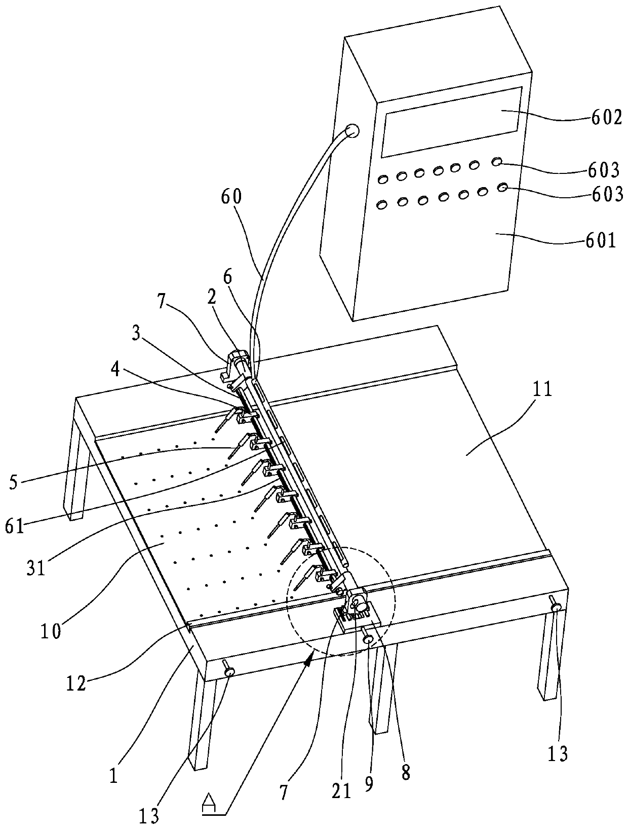
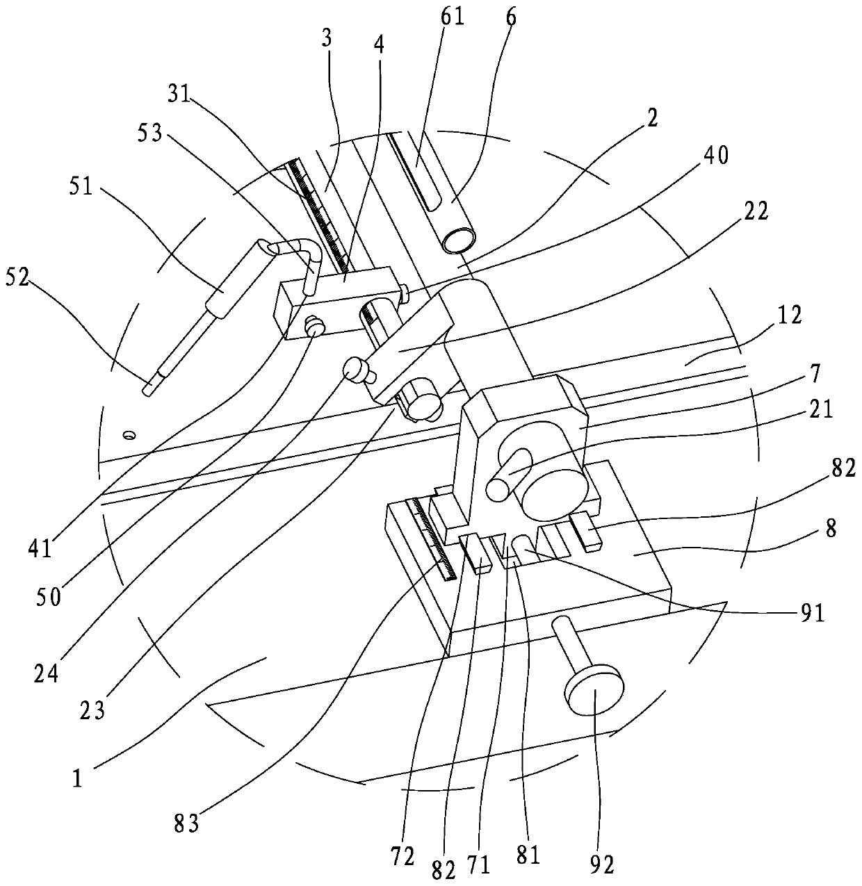
[0028] like Figure 1 to Figure 2 The rubber sheet cutting structure shown includes a workbench 1, which is provided with a concave flow channel 11 for the rubber sheet 10 to move longitudinally inside, and the workbench 1 is provided with an adjustable The adjustment plate 12 of the working width of the flow channel 11, and the adjustment screw 13 capable of adjusting the left and right positions of the adjustment plate 12 in the flow channel 11, by turning the adjustment screw 13, the adjustment plate 12 is driven to move left and right in the flow channel 11, and the adjustment plate is adjusted. 12 on the left and right positions of the flow channel, so that the working width of the flow channel 11 can be adjusted according to the rubber sheets 10 of different width specifications, so that one machine with multiple functions can be realized.

[0029] The workbench 1 is...


PUM


Abstract

The invention discloses a rubber plate cutting structure which comprises a worktable. A recessed flow channel is arranged on the worktable, a rubber plate can longitudinally move in the flow channel,a beam stretching over the flow channel is arranged on the worktable, a mounting rod is arranged on the beam, a plurality of mounting blocks capable of sliding and rotating on the mounting rod sleevethe mounting rod, first scale marks for axial sliding reference of the mounting blocks are arranged on the mounting rod, first locking screws for fixing the mounting blocks onto the mounting rod are arranged on the mounting blocks, electric heating cutting rods capable of cutting the rubber plate to form holes are arranged on the mounting blocks, a storage pipe for storing a cable is arranged on the beam and parallel to the beam, a plurality of leading-out holes for leading out the cable to be in circuit connection with the electric heating cutting rods are formed in the storage pipe, a left support and a right support for supporting the beam are arranged on two sides of the worktable, a wrench is arranged on the beam and pulls the beam to rotate, the electric heating cutting rods are driven to cut the rubber plate, and operation is facilitated.

Description

【Technical field】 [0001] The invention relates to a glue board cutting structure. 【Background technique】 [0002] At present, the method of processing small holes on rubber sheets generally uses cutting tools, and is divided into two types: manual cutting and equipment cutting. Manual cutting has low production efficiency and high labor intensity; equipment cutting generally includes single-hole cutting equipment and multi-hole simultaneous cutting equipment. , The production efficiency of single-hole cutting equipment is also low, and the multi-hole simultaneous cutting equipment is generally more complicated, and the equipment is expensive. [0003] The present invention is made based on this situation. 【Content of invention】 [0004] The object of the present invention is to overcome the disadvantages of the prior art, and provide a rubber sheet cutting structure with simple structure and convenient operation, which is used for hot-melt cutting the rubber sheet to form...

Claims


Application Information

Patent Timeline
Patent Type & Authority Patents(China)
IPC IPC(8): B26F1/24B26D7/01B26D7/06B26D7/10B26D7/26
CPCB26D7/01B26D7/06B26D7/10B26D7/2628B26F1/0084B26F1/24
Inventor 陈建军方敬丰赖双祥孙天正高晓华
Owner 广东邦达实业有限公司
Learn More