Rotation connector

A technology for rotating connectors and flat cables, applied in the direction of flexible/rotatable wire connectors, connections, electrical components, etc., can solve the problems of the total cost of rotating connectors, increase the cost of flat cables, and avoid cost increases. Effect

Active Publication Date: 2013-10-30
ALPS ALPINE CO LTD
View PDF5 Cites 14 Cited by
  • Summary
  • Abstract
  • Description
  • Claims
  • Application Information

AI Technical Summary

Problems solved by technology

That is, although the above-mentioned conventional rotary connector can reduce the total number of lead blocks, it in

Method used


Image

  • Rotation connector
  • Rotation connector
  • Rotation connector

Examples


Embodiment Construction

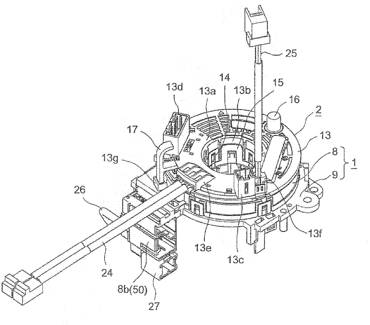
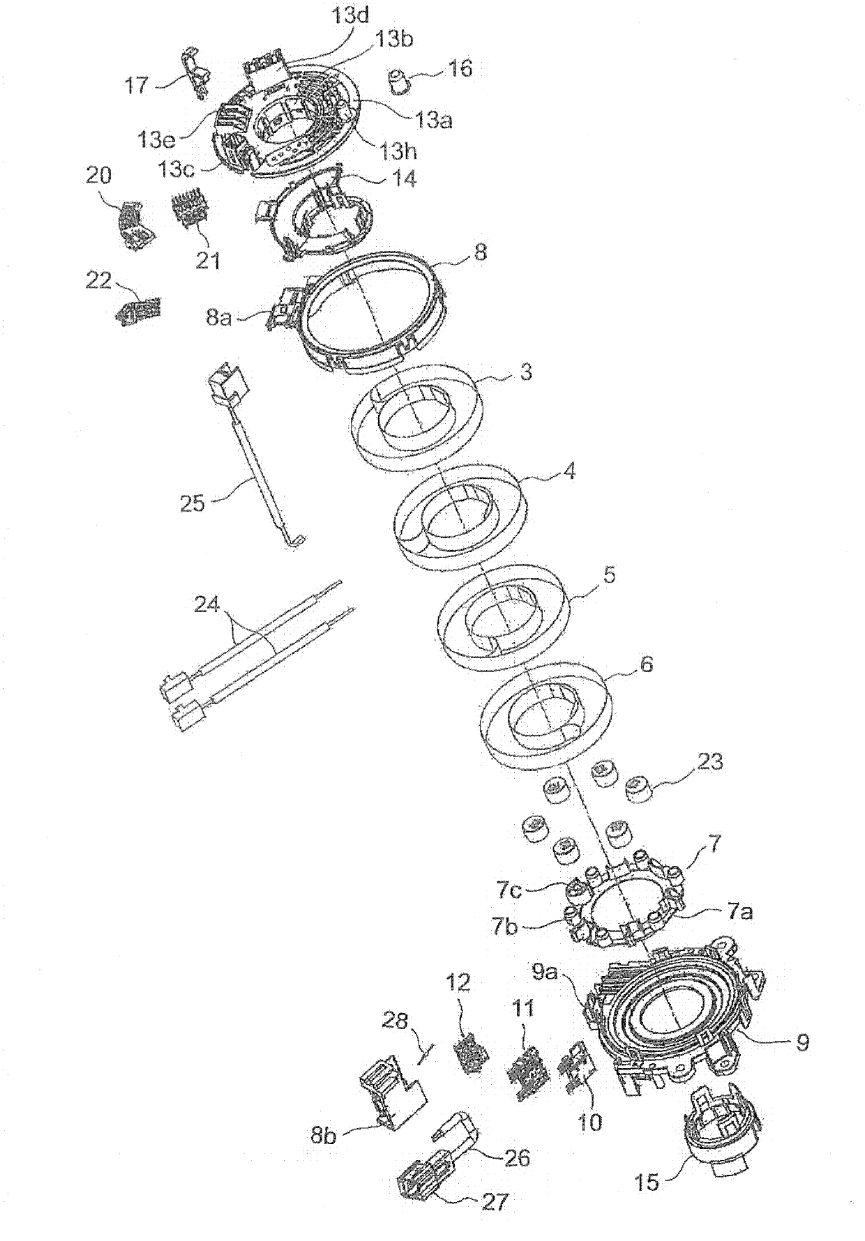
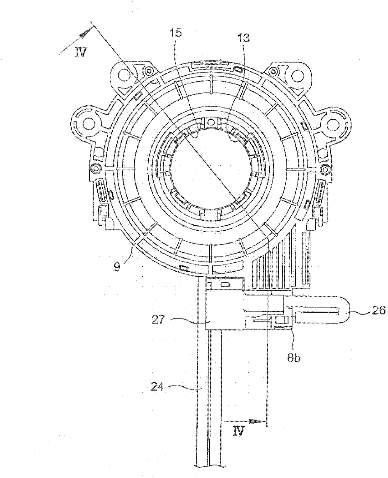
[0060] Hereinafter, embodiments of the invention will be described with reference to the drawings. Such as Figure 1 to Figure 5 As shown, the rotary connector according to the embodiment of the present invention mainly includes: a fixed-side housing 1; a movable-side housing 2 rotatably connected to the fixed-side housing 1; The flat cable 3, the flat cable 4, the flat cable 5 (the first flat cable), and the flat cable 6 (the second flat cable) in the annular space S divided between the housings 1 and 2; The first to third lead blocks 10 to 12 and the fourth to sixth lead blocks 20 to 22 respectively connected to the two ends of ~ 6 ; the bracket 7 arranged between the two housings 1 and 2 in a rotatable manner. This rotary connector is assembled and used in the steering device of the automobile, and the fixed side housing 1 provided on the steering rod (not shown) and the movable side connected to the steering wheel (not shown) are connected through each of the flat cables ...


PUM


Abstract

The invention provides a rotation connector with which two flat cables with wide-width strip conductors can be connected with a wire-leading block easily. End portions in the length direction of a first flat cable and a second flat cable (5, 6) are formed into shapes that are formed by cutting off sides in the width direction and enabling the strip conductors (19) to be exposed in the front end sides of the rest narrow-width portions (5a, 6a). The strip conductor (19) is connected with a pair of connection terminals (30) arranged in the wire-leading block (12 (or 22)) respectively. Besides, the end portions in the length direction of the first flat cable and the second flat cable (5, 6) are positionally overlapped with each other in a manner that the narrow-width portion (5a, (6a))of one flat cable is configured on a cut portion (6b (5b)) of the other flat cable. In the wire-leading block, the end portion which is adjacent to the cut portion (5b) and is in the length direction of the first flat cable (5) that is as a lower layer side bends towards the direction that is away from the narrow-width portion (6b) of the second flat cable (6) that is as an upper layer side.

Description

technical field [0001] The present invention relates to a rotary connector equipped in a steering device of an automobile and used as an electrical connection mechanism for an air bag system, and more particularly to a rotary connector using a plurality of flat cables carrying only one wide ribbon conductor. Connector. Background technique [0002] The rotary connector is briefly composed of a fixed-side housing, a movable-side housing, and a flat cable. The fixed-side housing has an outer cylindrical portion. body connection, the flat cable is accommodated in the annular space provided between the outer tube part and the inner tube part in a manner that can be wound tightly and uncoiled, and the two ends of the flat cable in the longitudinal direction are electrically connected to the lead block. connections and mechanical connections. A lead block is a component that holds a connection terminal on an insulating base by insert molding or the like, and is incorporated into...

Claims


Application Information

Patent Timeline
IPC IPC(8): H01R35/00
Inventor 高桥靖典高志鹏刘英杰
Owner ALPS ALPINE CO LTD
Why Eureka
Try Eureka