Quick clamping mechanism

A clamping device, fast technology, applied in the direction of workpiece clamping devices, clamps, manufacturing tools, etc.

Inactive Publication Date: 2013-11-13
陈瑞腾
View PDF12 Cites 4 Cited by
  • Summary
  • Abstract
  • Description
  • Claims
  • Application Information

AI Technical Summary

Problems solved by technology

[0005] As mentioned above, the problem to be solved by the present invention is to prevent quality defects such as noise and vibration caused by its instantaneous rebound.

Method used


Image

  • Quick clamping mechanism
  • Quick clamping mechanism
  • Quick clamping mechanism

Examples


Embodiment Construction

[0048] The present invention is further illustrated below with examples, but the present invention is not limited thereto.

[0049] Mechanism Explanation: This description takes the double thread sleeve as an example to show the function of two sets of left and right double threads with opposite helix angles, and then continues to explain the situation when the two sets of helix angles are separated into two places.

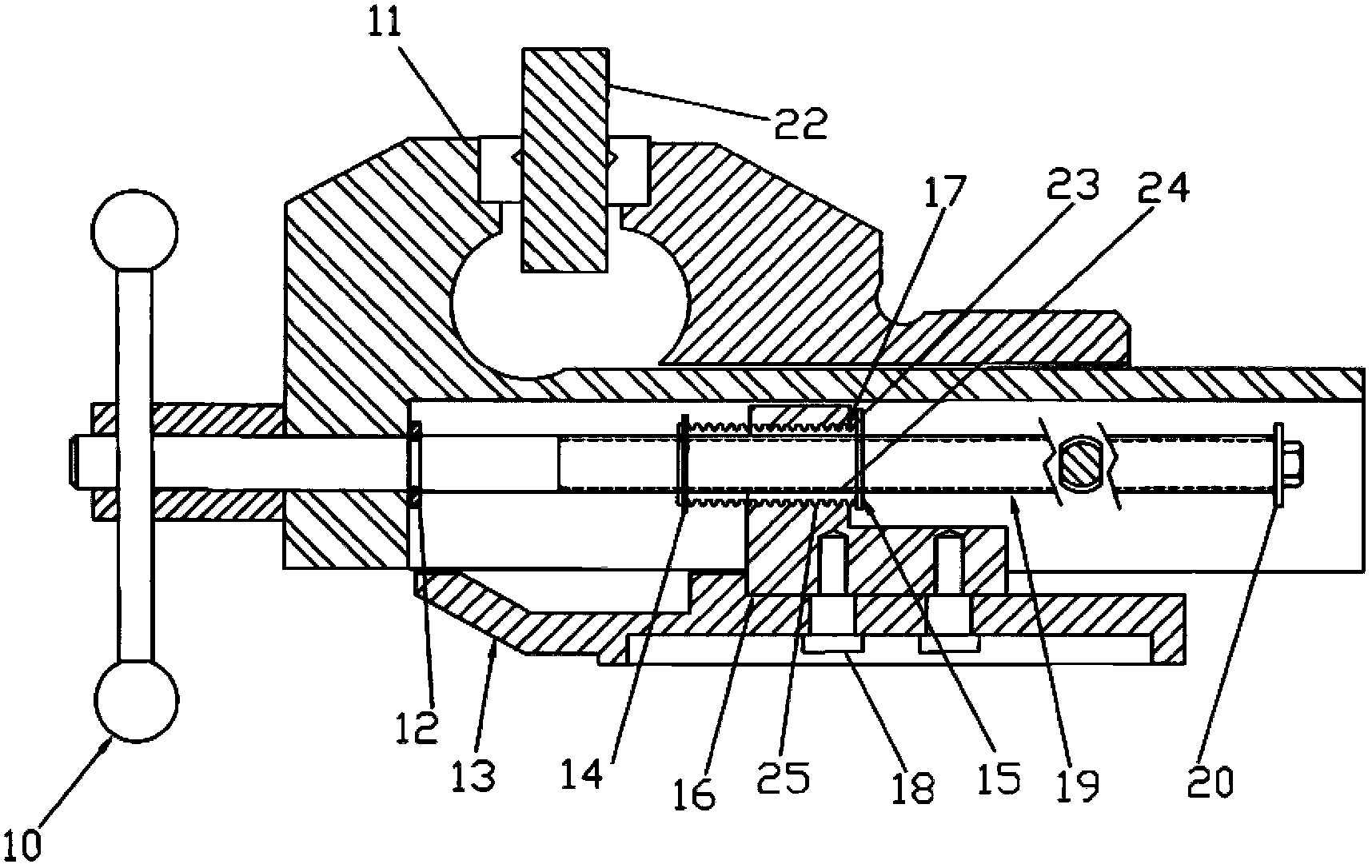
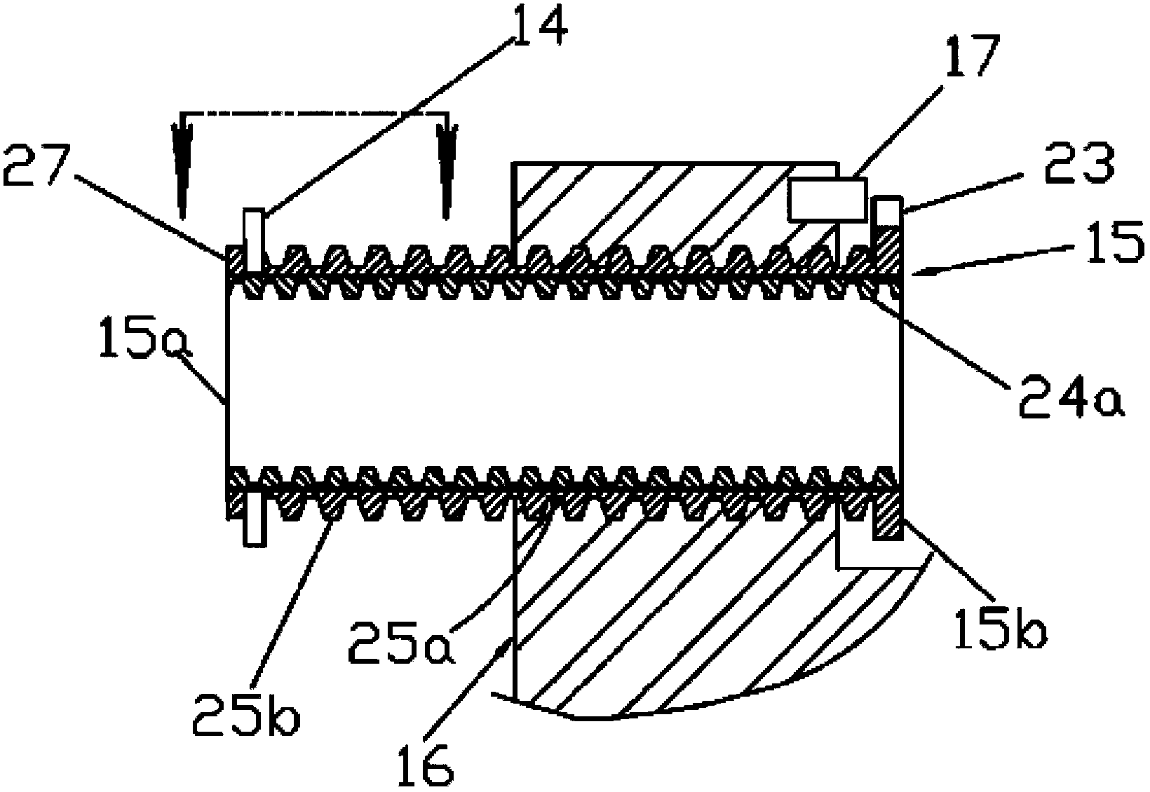
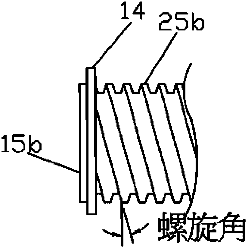
[0050] attached figure 1 It is shown that the whole quick vise uses two sets of thread sets with opposite left and right helix angles, one set is seated on the engaging thread set (24), and the other set is seated on the pressurizing thread set (25). These two sets of opposite helix angles are shown in the attached image 3 with attached figure 2 ,7 in. The engaging thread group (24) is called by the engagement of the internal thread (24a) of the double thread sleeve (15) and the external thread (24b) of the beveled screw (19); the pressurized thread group (2...


PUM


Abstract

A special quick clamping mechanism designed for increasing efficiency and improving the quality of clamping systems that can be used in various vises, C-clamps and all other clamping applications. This invention applies a concept of using two sets of opposing thread angles; one thread set is used at engagement, while the other is used at clamping. By using these two sets of opposing helix angles it creates opposing axial forces against each other, so as to force the clamping thread set to rotate first in the process of releasing a clamping force. This function would prevent a sudden drop in clamping force; a problem most quick clamping designs having in the industry. And, a collar jam preventing device that can stop a collar in the radial direction before it bumps into an axial dead end, which causes a tight jam and becomes hard to crank in the subsequent working cycle.

Description

technical field [0001] The invention relates to a quick clamping device, the specific technology of which is to use two groups of thread groups with opposite left and right helix angles. Grouped on the rotary pressurized thread group; in this way, the helix angles are opposite to each other to form a conflicting angle to determine the sequence of pressure release. This feature makes it possible to avoid noise and quality problems caused by instantaneous pressure release and rebound when the work piece is released after clamping the work piece and reversed to release the pressure under a large axial pressure. Another feature of the present invention is to use a radial blocking device to prevent the sleeve from thread self-locking due to the axial rotation to the bottom dead center when the sleeve moves axially. This technology can be convenient to avoid easy starting due to self-locking of the thread when starting the next work. Background technique [0002] At the beginnin...

Claims


Application Information

Patent Timeline
Patent Type & Authority Applications(China)
IPC IPC(8): B25B11/00
CPCB25B1/10B25B1/103B25B1/24B25B5/16B25B5/102
Inventor 陈瑞腾
Owner 陈瑞腾
Why Eureka
Try Eureka