Method for determining combustor vibration source position of combustion gas turbine

A determination method, gas turbine technology, applied in gas turbine engine testing, jet engine testing, etc.

Active Publication Date: 2013-11-13
BEIJING HUAQING GAS TURBINE & INTEGRATED GASIFICATION COMBINED CYCLE ENG TECH
View PDF5 Cites 1 Cited by
  • Summary
  • Abstract
  • Description
  • Claims
  • Application Information

AI Technical Summary

Problems solved by technology

However, these technologies did not start from the source of thermoacoustic oscillation in the combustion chamber to first determine the location of the vibration source, and then seek effective methods to control or suppress it

Method used


Image

  • Method for determining combustor vibration source position of combustion gas turbine
  • Method for determining combustor vibration source position of combustion gas turbine
  • Method for determining combustor vibration source position of combustion gas turbine

Examples


Embodiment Construction

[0031] The specific implementation of the present invention will be further described below with reference to the accompanying drawings and specific embodiments.

[0032] like figure 1 As described above, the present invention provides a method for determining the position of a vibration source in a combustion chamber of a gas turbine, the method including

[0033] Include the following steps:

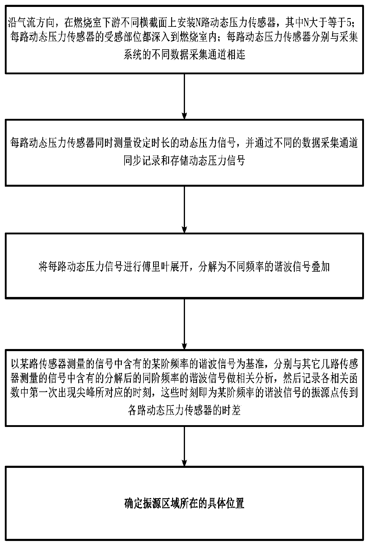
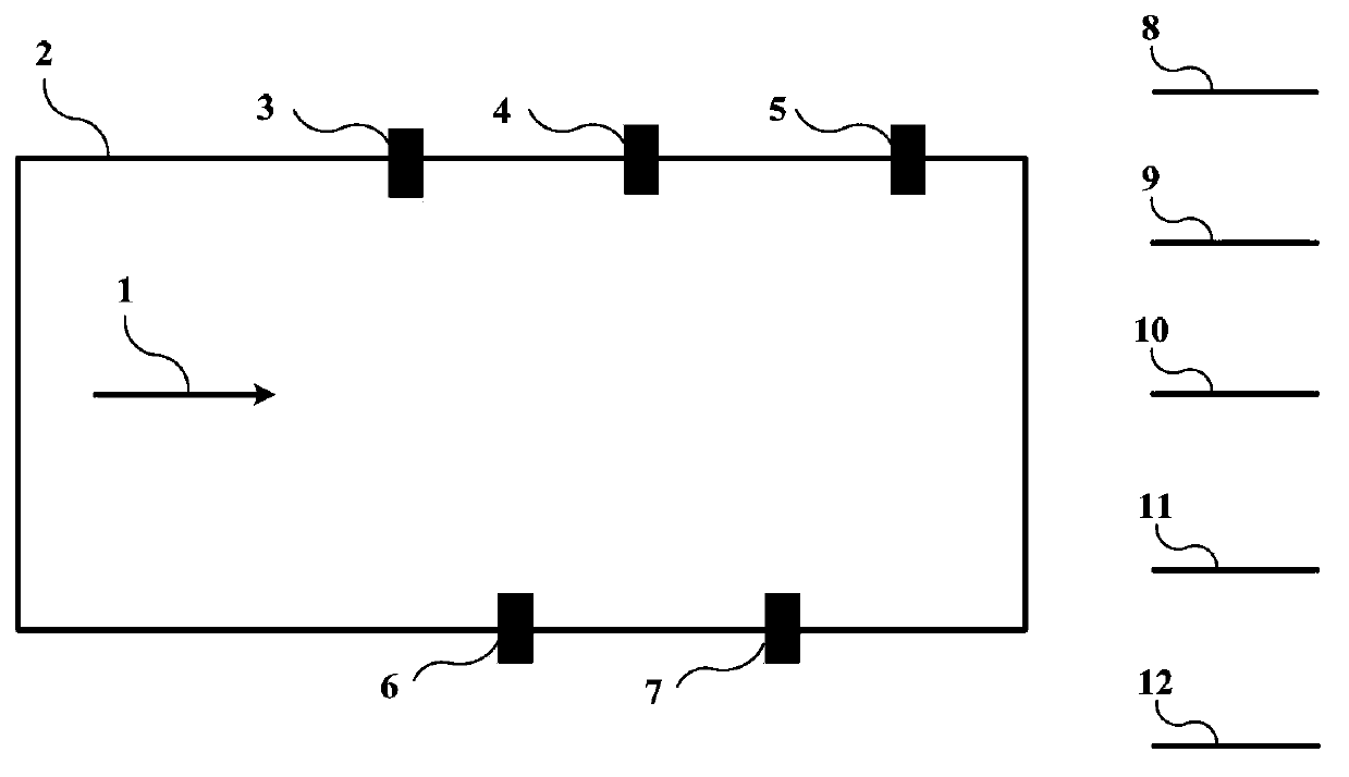
[0034] 1) Along the airflow direction, install N dynamic pressure sensors on different cross-sections downstream of the combustion chamber, where N is greater than or equal to 5; the sensing part of each dynamic pressure sensor goes deep into the combustion chamber; The different data acquisition channels of the system are connected;

[0035] 2) The N-channel dynamic pressure sensor simultaneously measures the dynamic pressure signal of the set duration t, and simultaneously records and stores the dynamic pressure signal through different data acquisition channels;
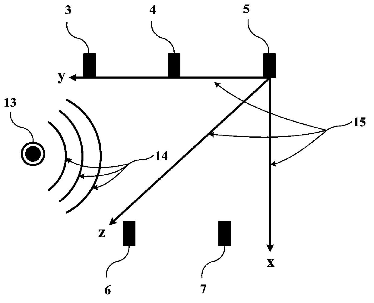
[0036] 3) Perfo...


PUM


Abstract

A method for determining a combustor vibration source position of a combustion gas turbine comprises the following steps: mounting a plurality of channels of dynamic pressure sensors at a plurality of positions in a combustor; connecting the sensors with various data collecting channels of a collecting system; measuring dynamic pressure signals in a set time period by each sensor simultaneously, and simultaneously recording and storing the signals through the data collecting channels; performing fourier expansion on the signals in each channel, and decomposing into harmonic signals with various frequencies to add; taking the harmonic signal of one frequency contained in the signals measured by one sensor as a standard, carrying out correlation analysis to the harmonic signals of the same frequency contained in the signals measured by other sensors respectively, and then recording the corresponding moment that a peak appears firstly in each correlation function, wherein the moment is the time difference transmitted to the sensors from the vibration source point of the harmonic signal of the frequency; finally determining the vibration source points of the harmonic signals of the various frequencies according to the transmission principle of the wave, wherein the gathering point of the vibration source points is the position of the vibration source area in the combustor.

Description

technical field [0001] The invention belongs to the technical field of gas turbine combustion chamber measurement and control, and in particular relates to a method for determining the position of a vibration source of a gas turbine combustion chamber. Background technique [0002] As the world pays attention to environmental protection issues, various countries have stricter and stricter requirements on emissions from gas turbine combustors, especially NOx. In order to reduce the emission of pollutants such as NOx, most modern gas turbine combustors adopt lean premixed combustion technology. Lean premixed combustion can easily cause thermoacoustic oscillations in the combustion chamber, which not only generate noise, but also do great harm to the safe operation of gas turbine equipment. In addition, thermoacoustic oscillations in the combustion chamber often interfere with the combustion process, which can lead to increased emissions of harmful substances. Therefore, duri...

Claims


Application Information

Patent Timeline
Patent Type & Authority Applications(China)
IPC IPC(8): G01M15/14
Inventor 谢法井文明
Owner BEIJING HUAQING GAS TURBINE & INTEGRATED GASIFICATION COMBINED CYCLE ENG TECH
Why Eureka
Try Eureka