Multi-beam single-pulse angle measuring method based on beam selection method
A single-pulse angle measurement and multi-beam technology, applied in the radar field, can solve the problems of low angle measurement accuracy, small coverage area, and small calculation amount, and achieve the effect of improving the angle measurement accuracy, small calculation amount, and increased calculation amount.
- Summary
- Abstract
- Description
- Claims
- Application Information
AI Technical Summary
Problems solved by technology
Method used
Image
Examples
Embodiment 1
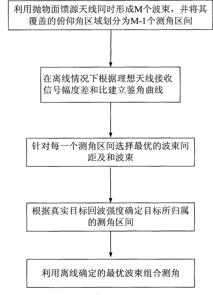
[0046] The invention is a multi-beam single-pulse angle measurement method based on a beam selection method. The angle measurement accuracy of the existing angle measurement method for ball-borne radar antennas is low. The present invention proposes a high-precision method for ball-borne radar antennas with large airspace coverage Angle measurement method, see figure 1 , including the following steps:
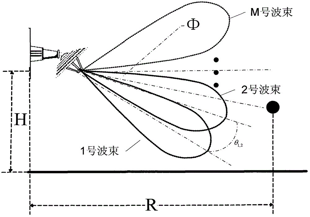
[0047] Step 1 Use the radar parabolic feed antenna to simultaneously form M beams and divide the covered airspace into M-1 angle measurement intervals: the angle between two adjacent beam axes is used as an angle measurement interval, and the M beams cover the airspace division results for θ 1,2 , θ 2,3 …theta i,i+1 , where 1≤i≤M-1, θ 1,2 is the angle between the beam axis of beam 1 and the beam axis of beam 2. The division of the airspace covered by M beams includes the following steps:
[0048] (1a) The feed source of the antenna is a plurality of horns, which are arran...
Embodiment 2
[0060] The multi-beam single-pulse angle measurement method based on the beam selection method is the same as that in Embodiment 1:
[0061] Step 1, use the parabolic feed antenna to simultaneously form M beams and divide the covered airspace into M-1 angle measurement intervals:
[0062] The feed source of the antenna is a plurality of horns, which are vertically arranged on the focal plane of the parabolic reflector, and each horn deviates from the focus one after another, so M beams partially overlapping each other are formed on the elevation plane, and the distance between two adjacent beams is 1°. It is convenient to use the target signal between two adjacent beam axes as an angle measurement interval. In this example, the radar antenna coverage airspace in the radar working interval with the target horizontal distance R and the radar erection height H is divided into θ 1,2 , θ 2,3 …theta i,i+1 , where 1≤i≤M-1, a total of M-1 angle measurement intervals, such as figur...
Embodiment 3
[0076] The multi-beam single-pulse angle measurement method based on the beam selection method is the same as that in Embodiments 1-2:
[0077] The feasibility and advantages of the present invention can be further illustrated by the following experiments.
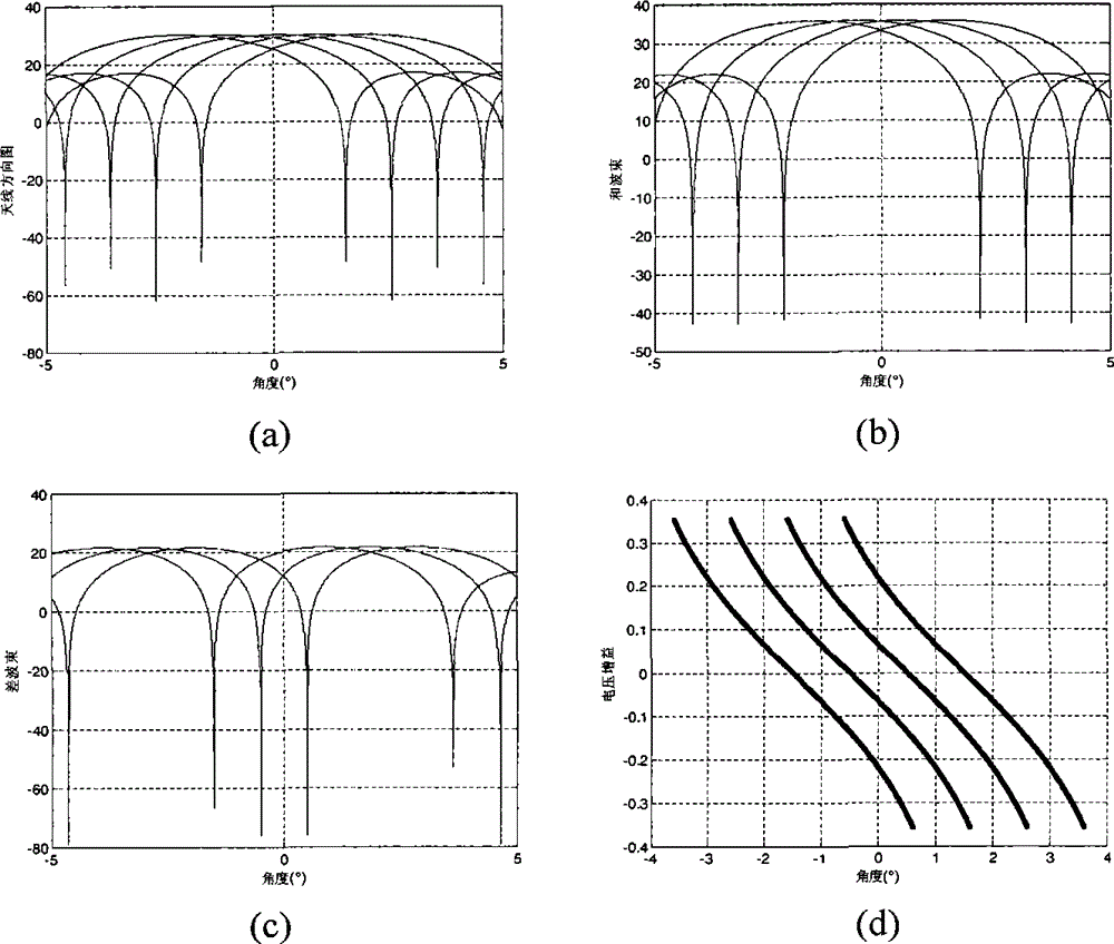
[0078] Now assume that the direction of the incoming wave of the target is the elevation angle Ф=-2°~2°, and the target signal arrives at an interval of 0.1°. Using computer simulation, 5 beams are formed at the same time, beams No. 1 to No. 5, and the distance between two adjacent beams is 1°. The maximum value of the beam points to the elevation angles of -2°, -1°, 0°, 1°, and 2° respectively. The signal-to-noise ratio in the two adjacent beamforming and beam channels is 25dB, and the noise is Gaussian complex noise. Experimental procedures and results as follows:
[0079] Select the two beams with a distance of 1° to do the sum difference, and the simulation diagram is as follows image 3 shown, where image 3 (a) is...
PUM
 Abstract
Description
Claims
Application Information
 - R&D
- Intellectual Property
- Life Sciences
- Materials
- Tech Scout
- Unparalleled Data Quality
- Higher Quality Content
- 60% Fewer Hallucinations
Browse by: Latest US Patents, China's latest patents, Technical Efficacy Thesaurus, Application Domain, Technology Topic, Popular Technical Reports.
© 2025 PatSnap. All rights reserved.Legal|Privacy policy|Modern Slavery Act Transparency Statement|Sitemap|About US| Contact US: help@patsnap.com


