Multi-beam single-pulse angle measuring method based on beam selection method

A single-pulse angle measurement and multi-beam technology, applied in the radar field, can solve the problems of low angle measurement accuracy, small calculation amount, and small coverage area, and achieve the effect of improving angle measurement accuracy, small calculation amount, and increasing calculation amount

Active Publication Date: 2013-11-13
XIDIAN UNIV
View PDF3 Cites 25 Cited by
  • Summary
  • Abstract
  • Description
  • Claims
  • Application Information

AI Technical Summary

Problems solved by technology

[0005] The purpose of the present invention is to solve the shortcomings of the existing two-beam single-pulse angle measurement technology with small airspace coverage and low angle measurement accuracy, and propose a high angle measurement accuracy and small calculation amount for the antenna hardware system with large airspace coverage. Multi-beam monopulse angle measurement method based on beam selection method

Method used


Image

  • Multi-beam single-pulse angle measuring method based on beam selection method
  • Multi-beam single-pulse angle measuring method based on beam selection method
  • Multi-beam single-pulse angle measuring method based on beam selection method

Examples


Embodiment 1

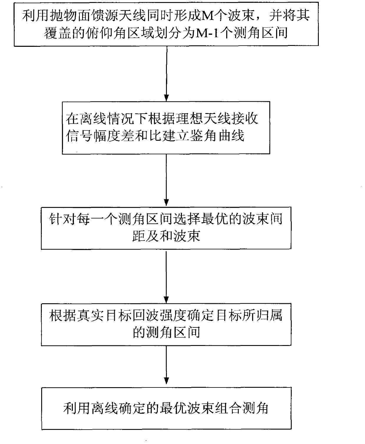
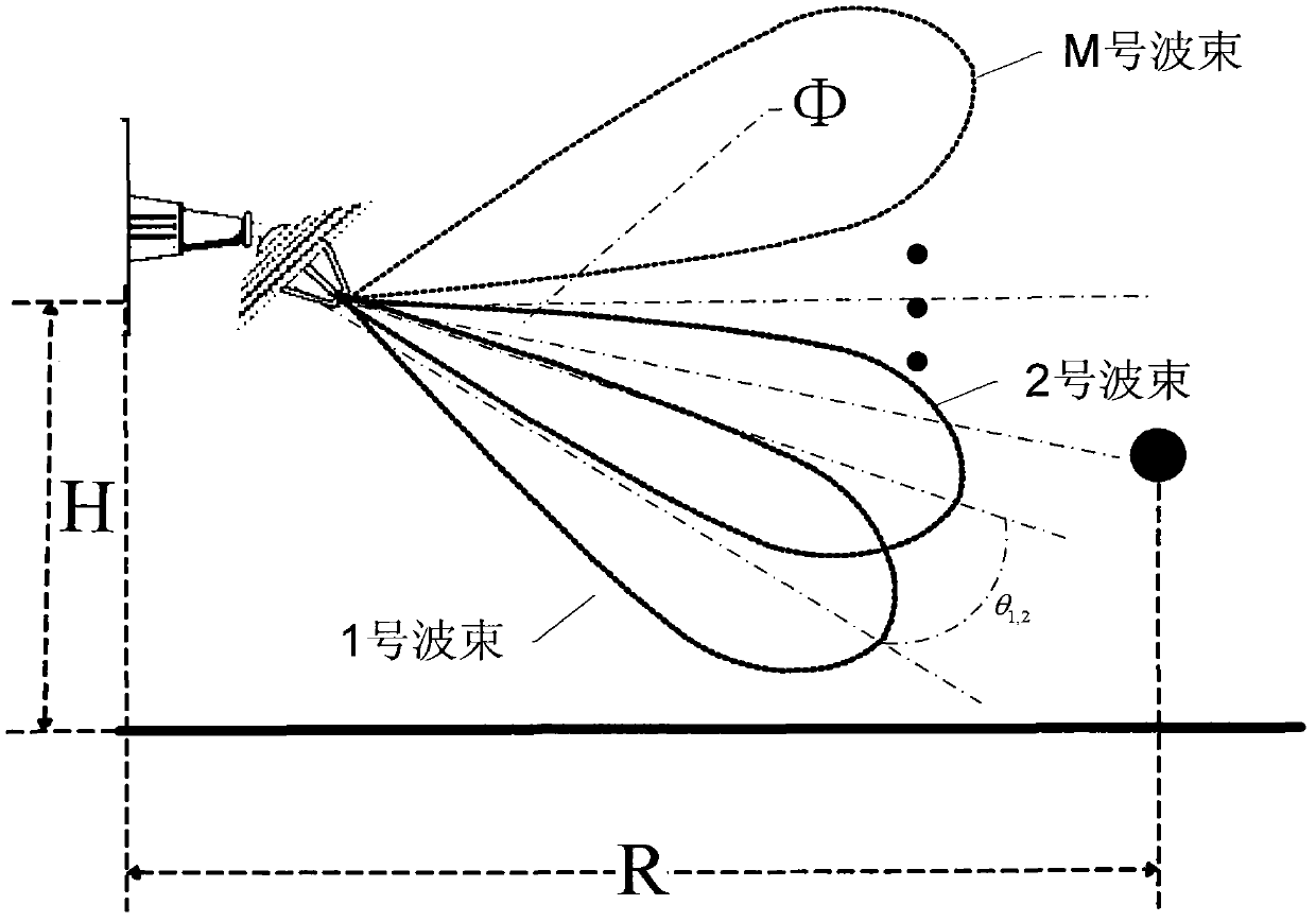
[0044] The invention is a multi-beam single-pulse angle measurement method based on a beam selection method. The angle measurement accuracy of the existing angle measurement method for ball-borne radar antennas is low. The present invention proposes a high-precision method for ball-borne radar antennas with large airspace coverage Angle measurement method, see figure 1 , including the following steps:

[0045] Step 1 Use the radar parabolic feed antenna to simultaneously form M beams and divide the covered airspace into M-1 angle measurement intervals: the angle between two adjacent beam axes is used as an angle measurement interval, and the M beams cover the airspace division results for θ 1,2 , θ 2,3 …theta i,j+1 , where 1≤i≤M-1, θ 1,2 is the angle between the beam axis of beam 1 and the beam axis of beam 2. The division of the airspace covered by M beams includes the following steps:

[0046] (1a) The feed source of the antenna is a plurality of horns, which are arran...

Embodiment 2

[0058] The multi-beam single-pulse angle measurement method based on the beam selection method is the same as that in Embodiment 1:

[0059] Step 1, use the parabolic feed antenna to simultaneously form M beams and divide the covered airspace into M-1 angle measurement intervals:

[0060] The feed source of the antenna is a plurality of horns, which are vertically arranged on the focal plane of the parabolic reflector, and each horn deviates from the focus one after another, so M beams partially overlapping each other are formed on the elevation plane, and the distance between two adjacent beams is 1°. It is convenient to use the target signal between two adjacent beam axes as an angle measurement interval. In this example, the radar antenna coverage airspace in the radar working interval with the target horizontal distance R and the radar erection height H is divided into θ 1,2 , θ 2,3 …theta i,i+1 , where 1≤i≤M-1, a total of M-1 angle measurement intervals, such as figur...

Embodiment 3

[0074] The multi-beam single-pulse angle measurement method based on the beam selection method is the same as that in Embodiments 1-2:

[0075] The feasibility and advantages of the present invention can be further illustrated by the following experiments.

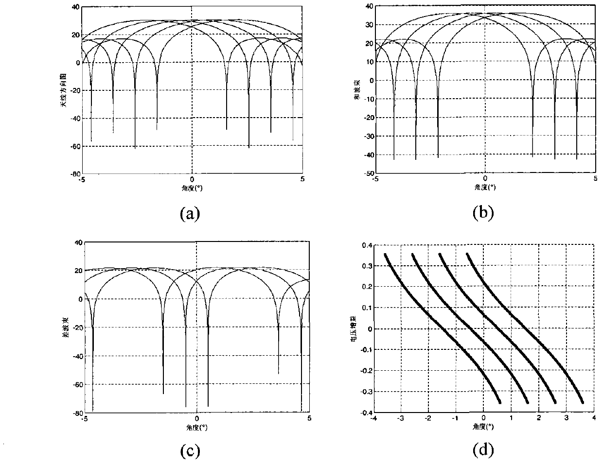
[0076] Now assume that the direction of the incoming wave of the target is the elevation angle Φ=-2°~2°, and the target signal arrives at an interval of 0.1°. Using computer simulation, 5 beams are formed at the same time, beams No. 1 to No. 5, and the distance between two adjacent beams is 1°. The maximum value of the beam points to the elevation angles of -2°, -1°, 0°, 1°, and 2° respectively. The signal-to-noise ratio in the two adjacent beamforming and beam channels is 25dB, and the noise is Gaussian complex noise. Experimental procedures and results as follows:

[0077] Select the two beams with a distance of 1° to do the sum difference, and the simulation diagram is as follows image 3 shown, where image 3 (a) is...


PUM


Abstract

The invention provides a multi-beam single-pulse angle measuring method based on a beam selection method. The method mainly solves the problem that two-beam single-pulse angle measurement is small in airspace covering range and low in accuracy under the condition of the existing hardware system. The method includes the following detection steps: 1) forming M beams simultaneously in pitching dimensions with each beam 1-degree larger than the last one and dividing the covered airspace into M-1 angle measuring sections; 2) building a discrimination angle curve under the off-line condition according to the ideal antenna receiving signal amplitude difference and ratio; 3) selecting the optimum beam distance and the optimum beam according to each angle measuring section theta i, i+1; 4) determining the affiliated angle measuring section theta i, i+1 according to the target echo strength; 5) determining the optimum angle measuring beam combination in an off-line mode through the step 3) and calculating difference and ratio of radar target echo received by the beam combination. The point that the difference and ratio corresponds to in the discrimination angle curve corresponding to the beam combination is the target angle. The method is small in calculation amount and high in angle measuring accuracy due to the fact that angle measurement is conducted by optimally selecting the optimum beam distance and the optimum beam under the condition of multiple beams.

Description

technical field [0001] The invention belongs to the technical field of radar, and relates to the detection of a target by a ball-borne radar, in particular to a multi-beam single-pulse angle measurement method based on a beam selection method, which is used for the angle detection of a low-altitude and ultra-low-altitude target by a ball-borne radar. Background technique [0002] Many actual combats have shown that cruise missiles have become an important weapon for long-distance precision strikes, posing a serious challenge to the survival and development of early warning and detection systems, and the key to its defense is detection and tracking, but affected by many factors, Ground-based radar cruise missile detection capabilities are limited, and it is difficult to meet operational needs. [0003] At present, the detection methods of cruise missiles are mainly concentrated in the two fields of using advanced radar detectors or airborne platforms and network detection of ...

Claims


Application Information

Patent Timeline
Patent Type & Authority Applications(China)
IPC IPC(8): G01S7/41G01S13/88
Inventor 苏洪涛刘宏伟王成海胡勤振刘子威
Owner XIDIAN UNIV
Why Eureka
Try Eureka