
Improved radiator used buckled fin

A snap-fit, radiator technology, applied in the direction of cooling/ventilation/heating transformation, etc., can solve the problems of excessive deformation, excessive deformation, difficult quality control, and complicated snap-fit ​​fin assembly.

Active Publication Date: 2013-11-20
刘静梅
View PDF12 Cites 0 Cited by
  • Summary
  • Abstract
  • Description
  • Claims
  • Application Information

AI Technical Summary

Problems solved by technology

The problem with the snap-fit ​​fins disclosed in ZL200820146622.5 is that in order to allow the embedding protrusion (5) to be embedded in the embedding through groove (4), especially for the positioning flap (502) to Going up and down through the embedded slot (4), it is necessary to deform the first pinch plate (21) and the second pinch plate (22) under the action of external force to eliminate interference during snap-fit ​​assembly. The first gusset (21) and the second gusset (22) are thin plates, and the operator often deforms the embedding protrusion (5) excessively due to excessive force when operating, and the embedding protrusion (5) is deformed after excessive deformation. The outer plane (501) of the convex part of the part (5) is no longer on the same plane as the outer surface (202) of the corresponding first pinch plate (21) and the second pinch plate (22), but is opposite to the first pinch plate (21) and the outer plane (202) of the second gusset (22) protrude
In this way, the radiator that is finally fastened and spliced, the plane formed by the outer plane (501) of the first gusset (21) and the second gusset (22) will be uneven, and in use, the first buckle The plate (21) and the outer plane (501) of the second pinch plate (22) are fastened to form a plane that will finally be attached to the heat dissipation flat surface of the heat source body. The first pinch plate (21) and the second pinch plate The outer plane (501) of (22) is buckled to form an uneven plane, which directly affects the heat dissipation effect of the radiator. At the same time, the buckling and assembling of such buckling fins in the prior art is obviously more complicated, and the quality is difficult to control. In summary, it is obvious that there is a need for further improvement in the prior art

Method used


Image

  • Improved radiator used buckled fin
  • Improved radiator used buckled fin
  • Improved radiator used buckled fin

Examples


Embodiment Construction

[0040] Hereinafter, the present invention will be further described in conjunction with an improved snap-fit ​​fin for a radiator provided by a preferred embodiment of the present invention and the accompanying drawings.

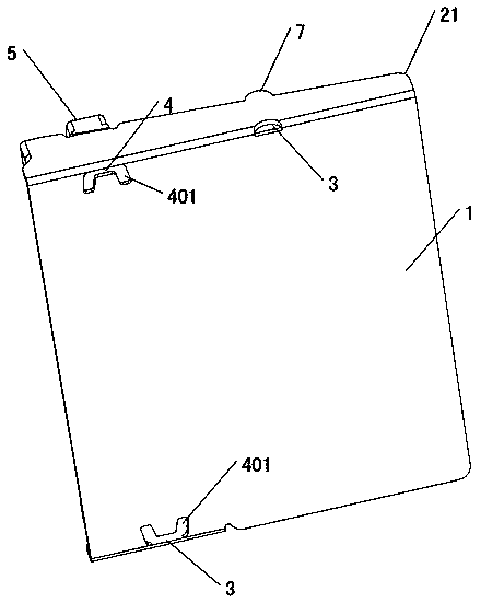
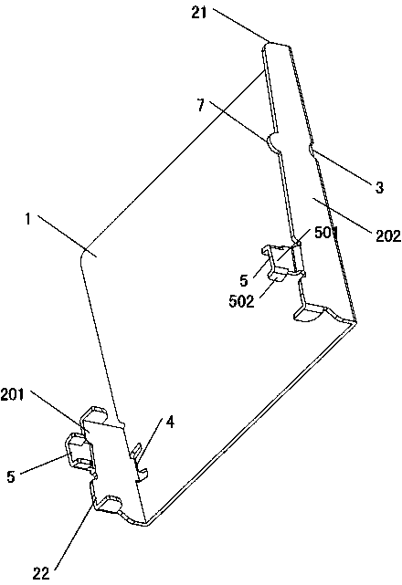
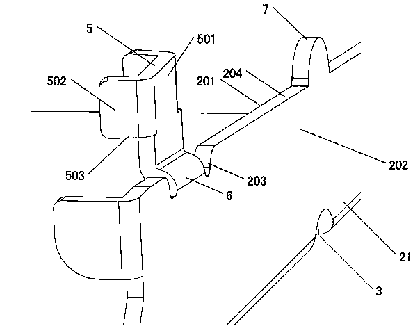
[0041] An improved snap-fit ​​fin for heat sink provided by the preferred embodiment of the present invention, as attached figure 1 , attached figure 2 , attached image 3 , attached Figure 4 , attached Figure 5 , attached Image 6 As shown, it includes a plate body 1 and an embedded card through groove 4. The opposite sides of the plate body 1 are bent to form a first buckle plate 21 and a second buckle plate 22. The first buckle plate 21 and the second buckle plate The outer sides 204 of the plates 22 are respectively connected with an embedding protrusion 5 adapted to the embedding through groove 4. The folded transition coupling part 6 is connected with the embedding protrusion 5, and the outer plane 501 of the embedding protrusion 5 on the firs...


PUM


Abstract

An improved radiator used buckled fin includes a plate body and an embedded clamping through groove, wherein a first buckling plate and a second buckling plate are formed through bending the two opposite sides of the plate body; an embedded clamping raised part matched with the embedded clamping through groove is linked with the outer side edge of each of the first buckling plate and the second buckling plate. The improved radiator used buckled fin is characterized in that the outer side edges of the first buckling plate and the second buckling plate are linked with the embedded clamping raised parts through inwards bent transition linking parts; the outer side planes of the embedded clamping raised parts on the first buckling plate and the second buckling plate are positioned within a parallel space defined by the inner side planes of the first buckling plate and the second buckling plate; the embedded clamping through groove is formed in the plate body. Compared with the prior art, the improved radiator used buckled fin improves the heat-conducting property of a radiator and improves the manufacturability of buckling assembly at the same time as the plane formed by the buckled first buckling plate and the second buckling plate is smoother.

Description

technical field [0001] The invention relates to an improved snap-fit ​​fin for a radiator, which belongs to the spliced ​​fin radiator component class. Background technique [0002] Radiators are widely used in many application fields such as electronics and LED lighting. Among radiators, finned radiators are an important product type. Among them, finned radiators formed by interlocking single fins Due to the lower cost of finned radiators made of integral molding, they occupy an important share in the market. The snap-fit ​​fins for radiators of the prior art were first disclosed by Chinese invention patent ZL200610035131.9, as attached Figure 8 As shown, the snap-fit ​​fins disclosed in ZL200610035131.9 are mostly made of aluminum alloy material and formed by integral die-casting. Structurally, it includes a plate body (1) and a tenon (S2), and the tenon ( The two sides of S2) are respectively provided with tenons (S201) and tenon holes (S202), and the tenons (S201) and ...

Claims


Application Information

Patent Timeline
IPC IPC(8): H05K7/20
Inventor 刘静梅
Owner 刘静梅
Learn More