
Control system and method for reciprocating compressors

一种控制系统、压缩机的技术,应用在泵控制、液体变容式机械、机械设备等方向,能够解决组件重量降低低速旋转操作振动水平等问题

Active Publication Date: 2013-11-20
EMPRESA BRASILEIRA DE COMPRESSORES SA (EMBRACO)
View PDF10 Cites 8 Cited by
  • Summary
  • Abstract
  • Description
  • Claims
  • Application Information

AI Technical Summary

Problems solved by technology

[0009] In designs where there are severe stress conditions, optimization of component weights, the need to significantly reduce vibration levels in low speed rotating operations, the solution to the spring design may not meet all desired conditions

Method used


Image

  • Control system and method for reciprocating compressors
  • Control system and method for reciprocating compressors
  • Control system and method for reciprocating compressors

Examples


Embodiment Construction

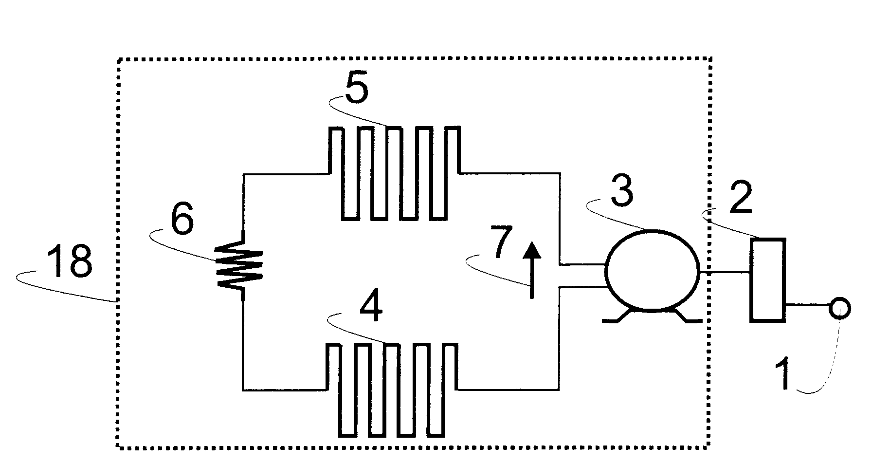
[0025] Such as figure 1 As shown, the cooling system comprises a reciprocating compressor 3 fed by an electrical power network 1 and having an electronic controller 2 able to control the operation of the reciprocating compressor 3 . The reciprocating compressor 3 drives the cooling gas in the gas circulation closed loop circuit 18 , thereby generating a cooling gas flow 78 within the circuit and directing this gas to the condenser 5 . After the condenser 5, the cooling gas passes through a flow cooling device 6, which may be, for example, a capillary tube. The gas is then directed to the evaporator 4 and then returned to the reciprocating compressor 3, restarting the gas circulation loop.

[0026] figure 2 Shows the focus of the subsystems inside the reciprocating compressor 3 formed by the housing 17 , the suspension spring 11 for damping the mechanical vibrations generated by the movement of the mechanical assembly 12 , the mechanical assembly is formed by a motor 9 and ...


PUM


Abstract

Control system for hermetic cooling compressor, which includes a reciprocating compressor and an electronic control (2) for the reciprocating compressor (3), the electronic control (2) being configured for, after commanding the turning off of the reciprocating compressor, detecting whether the turn velocity of the turning axle (10) is below a predefined velocity level, and then applying a braking torque that causes deceleration of the turning axle (10) before completing the next turn of the turning axle (10), in case the turn velocity detected is below the velocity level.

Description

technical field [0001] The present invention relates to a system and method enabling control of the stopping (braking) behavior of a reciprocating compressor. Background technique [0002] Reciprocating hermetic compressors include a connecting rod-crank and piston type with reciprocating motion, and are widely used in cooling equipment, domestic and commercial fields. [0003] Reciprocating compressors may be of the constant capacity type, where control of the two constant speed states (ON / OFF) is performed by switching the compressor on at maximum temperature and off at minimum temperature; or variable capacity Compressors, where the control is performed by some electromechanical device or electronic circuit capable of responding to a program dependent on a variable to be controlled (for example, the internal temperature of a compartment) on a cooling device, where The compressor functions in a reciprocating cycle of operation at varying speeds and when stopped. [0004]...

Claims


Application Information

Patent Timeline
Patent Type & Authority Applications(China)
IPC IPC(8): F04B35/04F04B49/02F04B49/06F04B49/10
CPCF04B2201/127F04B49/02F04B2201/1201F04B49/103F04B35/04F04B49/065F04B2201/0802F04B49/06F05B2210/12Y10S415/00Y10S417/00F04B49/20F04B2201/0201F04B2201/0209
Inventor M·G·施瓦滋F·古奥洛纳札里奥
Owner EMPRESA BRASILEIRA DE COMPRESSORES SA (EMBRACO)
Learn More