Conveyed bottle clamp for filling machine

A technology for conveying bottles and filling machines, which is applied in the field of conveying bottle clamps. It can solve the problems of not being able to clamp the mouth of the beverage bottle, placing the beverage bottle at an angle, and affecting the efficiency of filling, so as to achieve high filling efficiency and clamping The stable effect of beverage bottles

Active Publication Date: 2013-11-27
江苏普华盛包装科技有限公司
5 Cites 10 Cited by

AI-Extracted Technical Summary

Problems solved by technology

The disadvantage of this transmission bottle clamp is: on the one hand, the tightness of the two clamping arms in the transmission bottle clamp depends on the distance that the driving ends of the two clamping arms are stretched by the shift fork. It is made of rigid material and has no room for adjustment, and the shift fork is prone to wear and tear when it is in contact with the two clamping arms and the transition dial. The relatively shortened shift fork after wear will cause the transfer bottle clamp to loosen , it will not be able to clamp the mouth of the beverage bottle in severe cases; at the same time, because the clamping ends of the two cla...

Abstract

The invention discloses a conveyed bottle clamp for a filling machine. The conveyed bottle clamp comprises a bottom plate which is mounted below a mounting plate through two hinge pins, wherein each hinge pin is hinged with a clamping arm, the inner side wall of each clamping arm is provided with an arc-shaped opening right above the bottom plate, the two arc-shaped openings and the top surface of the bottom plate together form a driving pin positioning hole in which a driving pin is arranged, a second support post is arranged at the driving end of one of the clamping arms, a first support post is arranged on the bottom plate, a clamping arm opening/closing elastic mechanism is arranged between the first support post and the second support post, and the two clamping arms always trend to clamp the bottleneck of a beverage bottle by virtue of the clamping arm opening/closing elastic mechanism. When the driving end of the clamping arm provided with the second support post is pushed by an external force to rotate inwards, the clamping arm can push the driving pin to move forwards through the arc-shaped opening of the clamping arm so that the driving pin can push the clamping end of the other clamping arm to rotate outwards and open. The conveyed bottle clamp has the characteristics of stable clamping effect and high working efficiency.

Application Domain

Technology Topic

Image

  • Conveyed bottle clamp for filling machine
  • Conveyed bottle clamp for filling machine
  • Conveyed bottle clamp for filling machine

Examples

  • Experimental program(1)

Example Embodiment

[0014] The present invention will be further described below in conjunction with the drawings and specific embodiments.
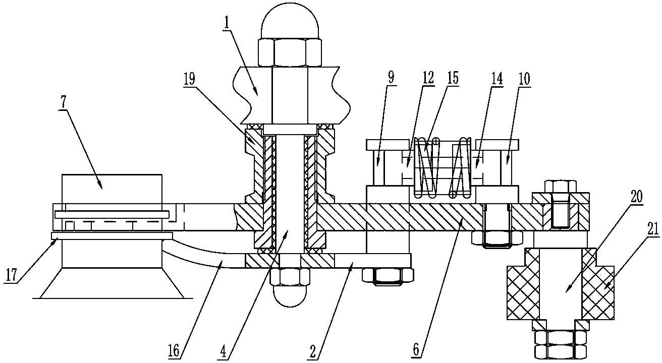
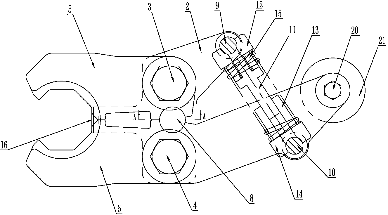
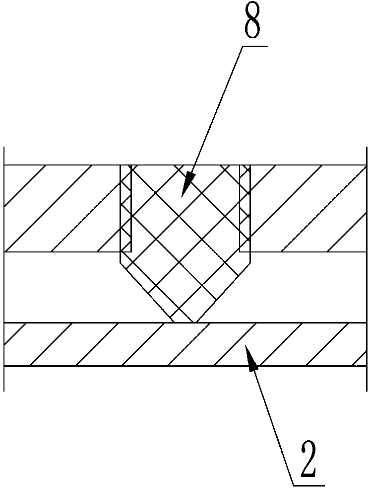
[0015] Such as figure 1 , figure 2 , image 3 As shown, the transfer bottle clamp on the filling machine includes a bottom plate 2 installed below the mounting plate 1 through a first pin 3 and a second pin 4, and a first clamp is movably provided on the first pin 3 Holding arm 5, a second clamping arm 6 is movably arranged on the second pin 4, and the clamping end of the first clamping arm 5 and the clamping end of the second clamping arm 6 can clamp the beverage in a relatively clamping manner Bottle mouth 7; on the inner side wall of the first clamping arm 5 is provided with an arc-shaped opening above the bottom plate 2, and on the inner side wall of the second clamping arm 6 is also provided with a circle above the bottom plate 2 The two arc-shaped openings are arranged opposite to each other to form a driving pin positioning hole. The driving pin 8 is movably arranged in the driving pin positioning hole. The lower end of the driving pin 8 is an inverted cone, which reduces the driving pin 8 and the bottom plate. The friction force between the upper surfaces of 2 increases the service life of the equipment; a second support column 10 is vertically arranged on the driving end of the second clamping arm 6 and a first support column 9 is vertically arranged on the bottom plate 2 , The first support column 9 and the second support column 10 are provided with a clamping arm expansion and closing elastic mechanism, the clamping arm expansion and closing elastic mechanism makes the clamping end of the first clamping arm 5 and the second clamping arm 6 The clamping end always has a tendency to clamp the mouth 7 of the beverage bottle; when the external force pushes the driving end of the second clamping arm 6 to rotate inward around the second pin 4, the clamping end of the second clamping arm 6 is synchronously driven to When the second clamping arm 6 rotates and opens, the second clamping arm 6 pushes the driving pin 8 to move forward through the corresponding arc-shaped opening, and the driving pin 8 synchronously pushes the clamping end of the first clamping arm 5 to rotate outwards and open, so that the A clamping arm 5 and a second clamping arm 6 loosen the bottle mouth 7 of the beverage bottle; when the external force exerted on the driving end of the second clamping arm 6 is removed, under the elastic force of the clamping arm opening and closing elastic mechanism , The driving end of the second clamping arm 6 rotates outwards around the second pin shaft 4, and while the clamping end of the second clamping arm 6 is synchronously driven to rotate inward, the second clamping arm 6 passes through the corresponding arc The opening pushes the driving pin 8 to move backward, and the driving pin 8 pushes the clamping end of the first clamping arm 5 to rotate inward, so that the clamping ends of the first clamping arm 5 and the second clamping arm 6 are closed together. Clamping the mouth of the beverage bottle 7; in this embodiment, the structure of the clamping arm elastic mechanism is: a first rocker 12 with a guide column 11, and a second rocker with a guide sleeve 13 14. The guide column 11 is movably arranged in the guide sleeve 13. The first rocker 12 and the second rocker 14 achieve relative telescopic movement through the cooperation of the guide column 11 and the guide sleeve 13, and the first rocker 12 and the second rocker A return spring 15 is sleeved on the rod 14. Under the action of the return spring 15, the outer end of the first rocker 12 is clamped on the first support column 9, and the outer end of the second rocker 14 is clamped on the second support. On the column 10, and the first rocker 12 and the second rocker 14 have a tendency to expand outward; this clamping arm expansion and closing elastic mechanism is not only convenient for installation and disassembly, but also improves the service life of the entire transmission bottle clamp In this embodiment, a bottle mouth retaining ring clip 16 is integrally extended on the bottom plate 2. When the first clamping arm 5 and the second clamping arm 6 clamp the beverage bottle mouth 7, the bottle mouth retaining ring clip The front end of the piece 16 is just against the mouth of the beverage bottle 7 At the same time, the front end of the bottle mouth retaining ring clip 16 just abuts the lower surface of the retaining ring 17 on the bottle mouth 7 of the beverage bottle, which not only prevents the beverage bottle from tilting during the process of placing the beverage bottle in the transfer bottle holder , It can also make the transfer bottle clamp more stable to the beverage bottle; in this embodiment, the first pin 3 between the first clamping arm 5 and the mounting plate 1, and the second clamping arm 6 and The shaft of the second pin 4 between the mounting plates 1 is fitted with a positioning column 19 respectively. The two positioning columns just press the two ends of the top surface of the driving pin 8 respectively, so as to avoid the driving pin 8 from being in the transmission bottle clamp. It is detached from the positioning hole of the driving pin during use, which improves the stability of the equipment; in this embodiment, a roller shaft is also vertically arranged on the driving end of the second clamping arm 6 equipped with the second support column 10 20. The roller shaft 20 is provided with a roller 21. In practical applications, the transfer bottle clamp is in contact with the transition wheel for pushing the second clamping arm 6 to rotate inward through the roller 21, which reduces the difference between the transfer wheel and the transition wheel. The frictional force between the equipment reduces the friction loss of the equipment and improves the overall service life of the equipment; in this embodiment, the clamping end of the first clamping arm 5 and the clamping end of the second clamping arm 6 are used The end surface of the mouth 7 of the beverage bottle is composed of several planes that can be tangent to the outer wall of the mouth 7 of the beverage bottle, so that the contact mode of the transfer bottle holder and the mouth 7 of the beverage bottle is changed from surface contact to multi-point contact. The point contact enables the transfer bottle clamp to not only firmly clamp the very regular round beverage bottle mouth 7, but also firmly clamp the irregular beverage bottle mouth.
[0016] The working principle of the present invention is as follows: when the transition wheel pushes the driving end of the second clamping arm 6 through the roller 21 to overcome the tension of the return spring 15 and rotates inwardly around the second pin 4, the second clamping arm 6 passes its corresponding The arc-shaped opening pushes the drive pin 8 forward. As the drive pin 8 moves forward, the drive pin 8 pushes the clamping end of the first clamping arm 5 around the arc-shaped opening of the first clamping arm 5. The first pin shaft 3 rotates outward to open; when the clamping end of the first clamping arm 5 and the clamping end of the second clamping arm 6 are mutually opened, the beverage bottle transfer device in the filling machine will The beverage bottle is placed in the clamping mouth formed by the clamping ends of the two clamping arms. At this time, the front end of the bottle mouth retaining ring clip 16 in the transfer bottle holder is just against the outer wall of the beverage bottle mouth 7, and the bottle mouth retaining ring The front end of the clip 16 just abuts the lower surface of the retaining ring 17 on the beverage bottle mouth 7; then the transition wheel will leave the roller 21 without applying external force to the second clamping arm 6, and the driving end of the second clamping arm 6 is at The return spring 15 rotates outwards around the second pin shaft 4 under the tension of the return spring 15 and pushes the drive pin 8 to move backward through its corresponding arc-shaped opening. As the drive pin 8 moves backward, the drive pin 8 passes through the first The arc-shaped opening of the clamping arm 5 pushes the driving end of the first clamping arm 5 to rotate outward to open, and synchronously drives the clamping end of the first clamping arm 5 to rotate inward, so that the first clamping arm 5 and The second clamping arm 6 clamps the bottle mouth 7 of the beverage bottle. Through the above operations, the operation of clamping or loosening the bottle mouth 7 of the beverage bottle by the transfer bottle clamp is completed, which not only holds the beverage bottle more firmly, but also greatly increase work productivity.

PUM

no PUM

Description & Claims & Application Information

We can also present the details of the Description, Claims and Application information to help users get a comprehensive understanding of the technical details of the patent, such as background art, summary of invention, brief description of drawings, description of embodiments, and other original content. On the other hand, users can also determine the specific scope of protection of the technology through the list of claims; as well as understand the changes in the life cycle of the technology with the presentation of the patent timeline. Login to view more.

Similar technology patents

Filling valve for container with wide mouth

Owner:江苏普华盛包装科技有限公司

Cupped drink cap-pressing machine

PendingCN109367850AGuaranteed continuity and uninterruptedImprove filling efficiencyPackagingFood packagingEngineering
Owner:广州市奥荣智能设备有限公司

Quantitative filling device for powder material

InactiveCN110849223AEfficient fillingImprove filling efficiencyFireworksFirecrackerStructural engineering
Owner:百特(福建)智能装备科技有限公司

Classification and recommendation of technical efficacy words

  • Improve filling efficiency

Pillar mining method for gentle dip thin ores

ActiveCN103967493AImprove filling efficiencyReduce filling cyclesUnderground miningSurface miningRoom and pillar miningComputer science
Owner:SANSHANDAO GOLD MINE SHANDONG GOLD MINING LAIZHOU

Culture medium split charging device for test tubes

InactiveCN104140066AImprove filling efficiencyGood liquidityFilling without pressureEngineeringCulture mediums
Owner:VEGETABLE RES INST OF SHANDONG ACADEMY OF AGRI SCI

Filling valve and process for filling materials using same

InactiveCN101734595AImprove accuracyImprove filling efficiencyBottle-handling machinesLiquid bottlingFilling materialsReturn channel
Owner:广州市德仕乐机械有限公司
Why Eureka
Try Eureka