
Gas dispenser and gas station composed of the same

A technology of gas filling machine and gas filling gun, applied in the field of gas filling station, can solve the problems of large investment, high power consumption, mechanical wear of compressors or hydraulic pumps, etc.

Active Publication Date: 2009-10-28
沈军
View PDF0 Cites 20 Cited by
  • Summary
  • Abstract
  • Description
  • Claims
  • Application Information

AI Technical Summary

Problems solved by technology

Compressor or hydraulic pump has mechanical wear, huge power consumption, and huge investment. Therefore, any improvement of the existing gas filling machine is to save the number of startups and working hours of the compressor or hydraulic pump.

Method used


Image

  • Gas dispenser and gas station composed of the same
  • Gas dispenser and gas station composed of the same
  • Gas dispenser and gas station composed of the same

Examples


Embodiment 1

[0094] Technical solution 1:

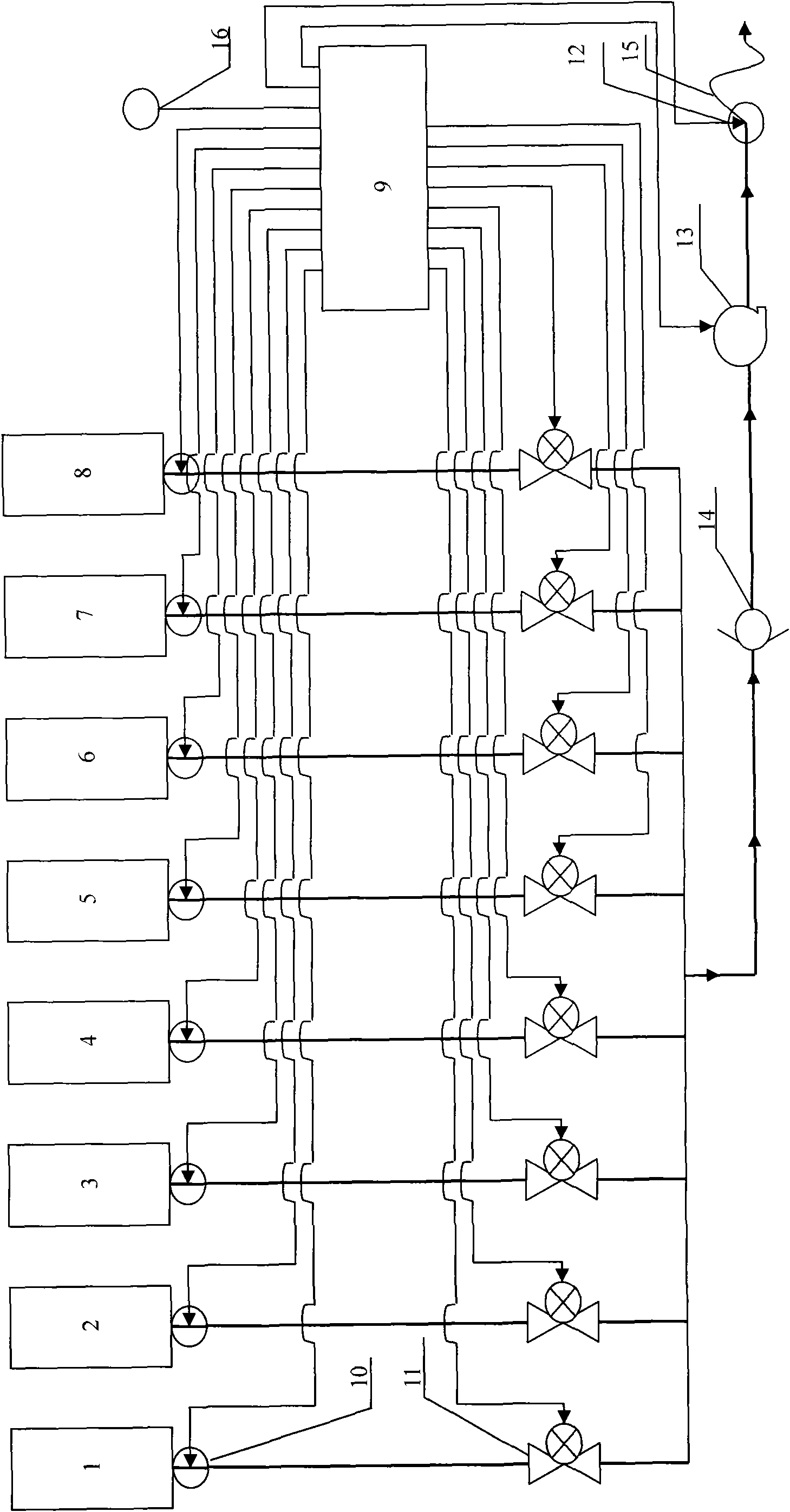
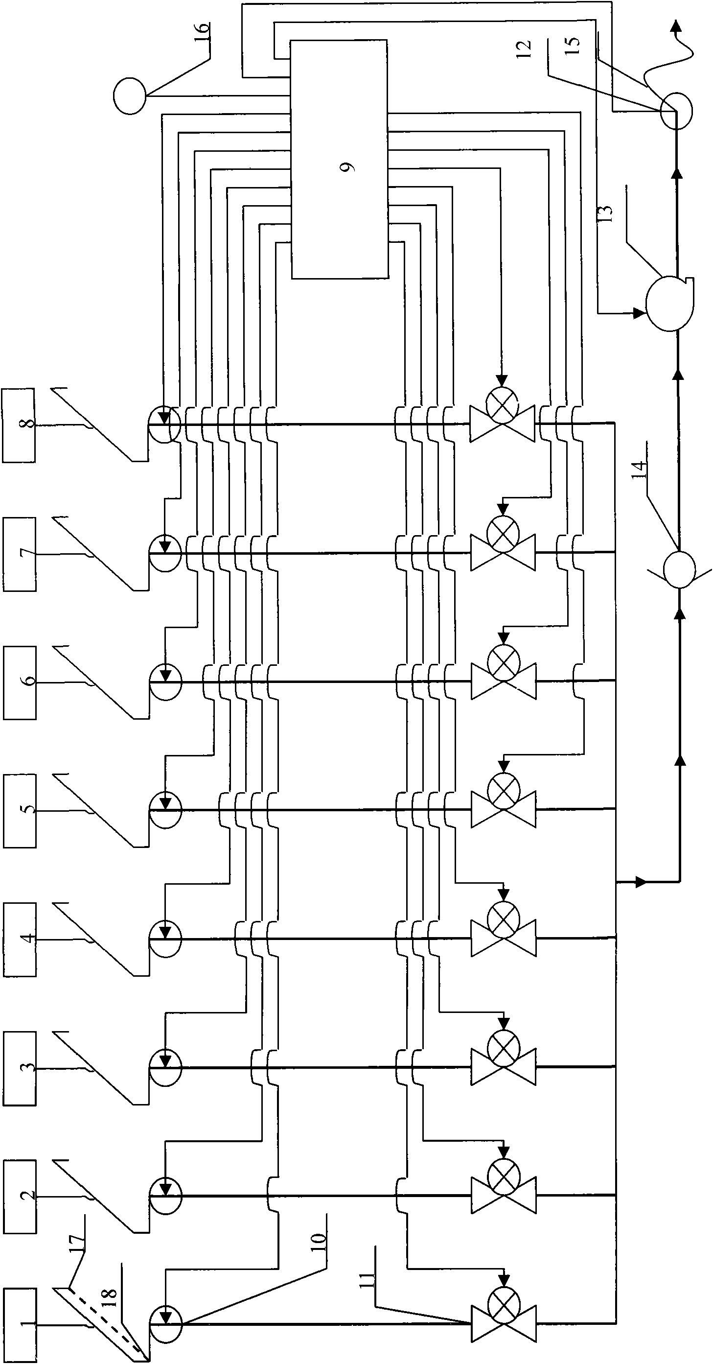
[0095] The gas path under the multi-gas bottle mouth is a single-channel pipeline, and the sensors and valves are installed on the single-channel pipeline, and the corresponding sensors and valves are connected in parallel and then connected in series with the metering device and the gas filling gun;

[0096] or,

[0097] The gas path under the multi-gas cylinder mouth is divided into multiple outlet pipelines in parallel. Sensors and valves are installed on the corresponding multi-channel pipelines. One of the metering device and the air gun is connected in series;

[0098] Connected with PLC and under its control, it constitutes a single-gun or multi-gun gas dispenser;

[0099] Its technical features are: PLC first collects the pressure value of the pressure sensor in the air gun, that is, the pressure value in the automobile gas cylinder, plus a set value, 0 < set value < 20, the sum of the sum is added to the multi Compare the pressure val...

Embodiment 2

[0120] Technical solution 2:

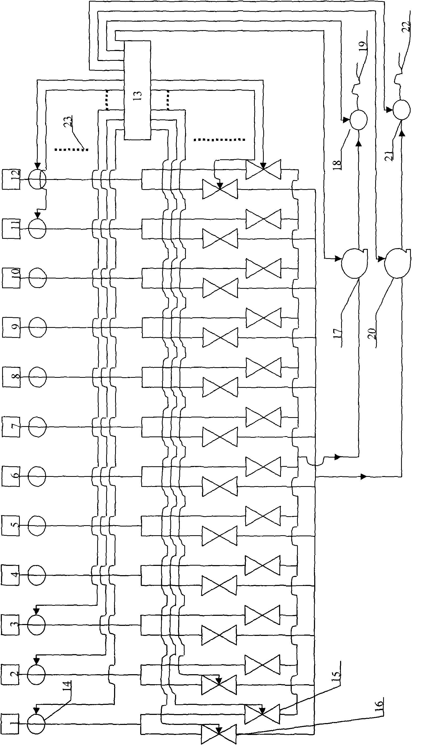
[0121] The gas filling station is composed of multiple gas cylinders and gas filling machines. Its technical features are: multiple gas cylinders alternately provide high-pressure gas, which meets the continuous filling volume of single or multiple guns of the gas filling machine for automobile gas cylinders.

[0122] Multi-gas cylinders alternately circulate to provide high-pressure gas technical features:

[0123] One or a group of gas cylinders in the multi-gas cylinder needs multiple or one or more groups of gas cylinders behind it to provide high-pressure gas for use. The set value is less than 12MPa, remove the parent gas filling station and fill up with high-pressure gas, then connect it again or directly connect another gas cylinder or group of gas cylinders filled with high-pressure gas, which is the first gas cylinder or group of gas cylinders after the last round Provide high pressure gas;

[0124] For the first cylinder or group of ...


PUM


Abstract

A gas dispenser is technically characterized in that a PLC firstly collects the pressure value of a pressure sensor in a gas dispersion gun, namely the pressure value in a vehicular gas cylinder. Then the pressure value is added with a preset value, wherein 0<the preset value <20. The summation is compared with the pressure value of each pressure sensor under a plurality of gas cylinder openings. The valve corresponding with the pressure value which is most approximative to and larger than the summation is opened for dispensing the gas through pressure difference. The steps are adopted again before balancing or after balancing. The steps are repeated until the value of the pressure sensor in the gas dispersion gun is the rated pressure value of the vehicular gas cylinder, wherein the rated pressure value is smaller than or equal to 20MPa. Then the valve is closed and the gas dispensation is finished. The gas station of the invention is composed of a plurality of gas cylinders and gas dispensers. The gas station is technically characterized in that the plurality of gas cylinders are used circularly for providing the high-pressure gas for satisfying the using amount of continuous gas dispensation of a single gun or a plurality of guns to the vehicular gas cylinder. The invention changes the technical route of prior gas substation. The matching of large-scale power devices of compressor and hydraulic pump is not required. The gas dispenser has no mechanical wear and extraordinarily low current consumption. The gas dispenser of the invention is the developing direction of the future.

Description

technical field [0001] A gas filling machine of the present invention and the gas filling station composed of it have changed the technical route of the existing sub-gas filling stations, and use multiple gas cylinders to alternately circulate to provide high-pressure gas to independently complete the filling of automobile gas cylinders, breaking away from compression The working mechanism of machine and hydraulic pump belongs to the field of gas filling equipment and automatic control. Background technique [0002] The present invention is applicable to various gases, and this case is illustrated with natural gas as an example. [0003] At present, in compressor-type or hydraulic-pump-type gas filling stations, the gas filling machines are filled with natural gas from the low, medium and high pressure gas storage tanks on the site of the gas filling station. When the pressure is insufficient, the compressor skid or the hydraulic pump skid of the gas filling station will ta...

Claims


Application Information

Patent Timeline
Patent Type & Authority Applications(China)
IPC IPC(8): F17C5/00F17C13/02B60S5/02
CPCF17C5/005F17C2205/0323F17C2221/033F17C2223/0123F17C2227/0135F17C2227/0157F17C2250/032F17C2250/0636
Inventor 沈军
Owner 沈军
Learn More