
Light source device

A light source device and light source technology, applied in light sources, electric light sources, lighting devices, etc., can solve the problems of high material cost, poor dimming efficiency, and inability to adjust local brightness of light, so as to improve dimming efficiency and change optical characteristics Effect

Inactive Publication Date: 2015-07-15
DARWIN PRECISIONS CORP
View PDF5 Cites 0 Cited by
  • Summary
  • Abstract
  • Description
  • Claims
  • Application Information

AI Technical Summary

Problems solved by technology

In other words, the variable resistor cannot adjust the local brightness of the light on the projected object
Furthermore, the existing lamps are likely to cause problems of high material cost and poor dimming efficiency

Method used


Image

  • Light source device
  • Light source device
  • Light source device

Examples


Embodiment Construction

[0044] According to a specific embodiment of the present invention, a light source device is provided to improve dimming efficiency.

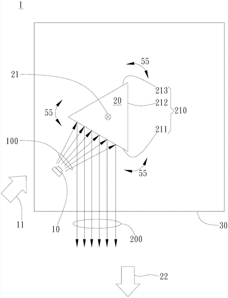
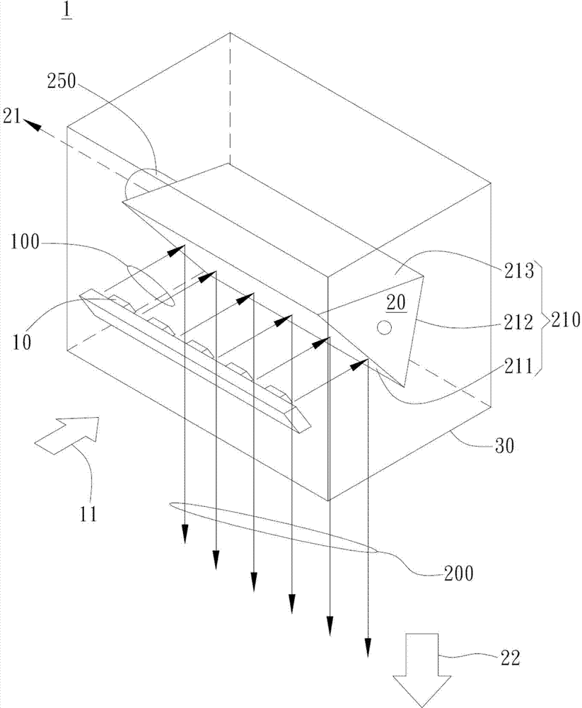
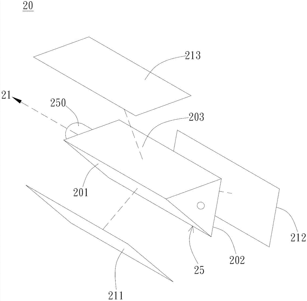
[0045] Please refer to Figure 1A , Figure 1A It is a schematic diagram of an embodiment of the light source device of the present invention. Such as Figure 1A As shown, the light source device 1 includes a light source 10 and a light modulating device 20 , wherein the light source 10 can be a light emitting diode light source or other point light sources or line light sources. In this embodiment, the light source 10 is a white LED light source, but not limited thereto. It should be noted that the light source 10 generates initial light rays 100 , wherein the initial light rays 100 enter the incident area along the first direction 11 on average. Specifically, the incident area is the space where the light source 10 faces the light modulating device 20 , and there is no object that can block the optical path of the initial light 100 . In pra...


PUM


Abstract

The invention provides a light source device, comprising a light source and a light modulation device. The light source generates initial light. The light modulation device comprises a light modulation reflecting surface for receiving the initial light and reflecting the initial light to change the initial light into modulated light. In the actual situation, the initial light reaches the light modulation reflecting surface in an incident region, and multiple light modulation reflecting regions are formed on the light modulation reflecting surface and provide adjustments of different levels directed at light modulation characteristics, respectively. The light modulation reflecting regions selectively enter the incident region with respect to an alternating axial direction and reflect the initial light to change the initial light into the modulated light. The alternating axial direction is parallel to the light modulation reflecting surface.

Description

technical field [0001] The invention relates to a light source device, in particular to a light source device capable of improving dimming efficiency and adjusting brightness. Background technique [0002] Generally speaking, an existing polychromatic light fixture includes multiple light sources and a controller, wherein each light source has a different color, and the controller controls the color output of the light sources. However, once the color of the light source is frequently switched, the controller is likely to generate excessive power, which will invisibly cause a burden on the battery. In addition, most of the current light sources use light-emitting diodes (LEDs), which have the advantages of saving electricity and low power. However, the above-mentioned lamp cannot use a single-color light source to generate illumination light of different colors, so many light sources are required to form the lamp, and it is difficult to reduce the material cost. [0003] I...

Claims


Application Information

Patent Timeline
Patent Type & Authority Patents(China)
IPC IPC(8): F21S2/00F21V14/04F21V9/16F21Y101/02
Inventor 枋定纬张忠兴黄子健
Owner DARWIN PRECISIONS CORP
Learn More